Land Rover Body And Paint Air Bag And Safety Belt Rover Manual
Here you can view all the pages of manual Land Rover Body And Paint Air Bag And Safety Belt Rover Manual. The Land Rover manuals for Automobile are available online for free. You can easily download all the documents as PDF.
Page 1
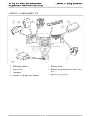
COMPONENT LOCATIONS, SHEET 1 OF 2
SRS warning indicator1
Driver air bag2
Clockspring3
Passenger air bag deactivation indicator4
Passenger air bag5
Passenger air bag deactivation switch (all except
NAS)
6
Restraints control module7
(G421346) Technical Training254
Lesson 3 – Body and PaintAir Bag and Safety Belt Pretensioner
Supplemental Restraint System (SRS)
Page 2
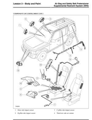
COMPONENT LOCATIONS, SHEET 2 OF 2
Door side impact sensor1
B pillar side impact sensor2
C pillar side impact sensor3
Third row side air curtain4
Air Bag and Safety Belt Pretensioner
Supplemental Restraint System (SRS)
Lesson 3 – Body and Paint
255Technical Training (G421346)
Page 3
First and second row side air curtain5
Safety belt pretensioner and buckle switch6
Seat position sensor7
Occupant classification module (NAS only)8
Seat cushion pressure sensor (NAS only)9
Seat cushion pressure pad (NAS only)10
Safety belt tension sensor (NAS only)11
Side air bag12
Front impact sensors13
GENERAL
The Supplemental Restraint System (SRS) provides
additional protection for occupants in certain vehicle
accident conditions. The SRS consists of:
•A driver air bag
•A passenger air bag
•A side...
Page 4
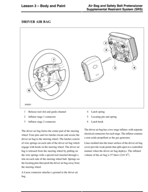
DRIVER AIR BAG
Release tool slot and guide channel1
Inflator stage 1 connector2
Inflator stage 2 connector3
Latch spring4
Locating pin and spring5
Latch hook6
The driver air bag forms the center pad of the steering
wheel. Four pins and two latches locate and secure the
driver air bag to the steering wheel. The latches consist
of wire springs on each side of the driver air bag which
engage with hooks in the steering wheel. The driver air
bag is released from the steering wheel by pulling on
the wire...
Page 5
PASSENGER AIR BAG
Reinforcement lid1
Chute2
Passenger air bag3
In-vehicle crossbeam4
Mounting bracket5
Lucar connector
Inflator connector6
Deployment doors7
The passenger air bag is located in the instrument panel,
behind the upper glove compartment. The bottom of the
passenger air bag is attached to a mounting bracket on
the in-vehicle crossbeam. The top of the passenger air
bag is attached to a chute, which, in turn, is attached to
a reinforcement lid in the top of the instrument panel.
When the air...
Page 6
Inflator4
A side air bag is attached to the outside of each front
seat backrest frame, under the backrest cover.
The side air bags are handed, and each consist of a
molded plastic case which contains the folded air bag
and the inflator. A cable connects the igniter of the
inflator to a connector in the main seat harness connector
block located under the front edge of the seat cushion.
When the air bag deploys it forces the front edge of the
molded plastic case apart and splits open the backrest
cover....
Page 7
Securing screws7
Active tether device8
Rear tether anchor9
Rear tether10
Cant rail clip11
Gas guide pipe12
Inflator electrical connector13
Inflator14
Inflator mounting bracket15
The first and second row side air curtains are installed
on the cant rails above the front and rear doors, behind
the headliner.
Each side air curtain has an inflator, which is attached
to the header rail by a mounting bracket and two screws.
The inflator is connected to the air curtain by a gas guide
pipe.
The gas guide pipe and...
Page 8
Third Row Side Air Curtain
NOTE: Right side air curtain shown, left side air curtain is mirror image
Securing screw1
Air curtain2
Securing screw3
Rear tether4
Gas guide pipe5
Inflator mounting bracket6
Inflator7
Rear tether anchor8
Tether housing9
Rear tether10
Front tether anchor11
The third row side air curtains are installed on the cant
rails above the rear quarter windows, behind the
headliner.
Each side air curtain has an inflator, which is attached
to the D pillar by a mounting bracket and two...
Page 9
PRETENSIONERS
Safety belt buckle1
Boot2
Anchor bolt3
Piston and tube4
Electrical connectors for inflator and buckle
switch
5
The pretensioners are used to tighten the front safety
belts during a collision to ensure the occupants are
securely held in their seats. A pretensioner is integrated
into each front safety belt buckle.
Each pretensioner has a tube containing an inflator and
a piston. The inflator is connected to the restraints
control module. The piston is attached to a steel cable,
the opposite...
Page 10
Each impact sensor incorporates an accelerometer and
a microcontroller powered by a feed from the restraints
control module. The power feed also provides the
interface connection through which the side impact
sensor communicates with the restraints control module
using serial data messages. Acceleration is evaluated
by the microcontroller and transmitted to the restraints
control module, which then makes the decision on
whether or not to activate the air bags and pretensioners.
When the ignition is...


