Home
>
American Water Heater
>
Gas Heater
>
American Water Heater High Efficiency Commercial Gas HCG Series AHCG3 119T 300 THRU AHCG3 119T 500 Series 200 201 User Manual
American Water Heater High Efficiency Commercial Gas HCG Series AHCG3 119T 300 THRU AHCG3 119T 500 Series 200 201 User Manual
Here you can view all the pages of manual American Water Heater High Efficiency Commercial Gas HCG Series AHCG3 119T 300 THRU AHCG3 119T 500 Series 200 201 User Manual. The American Water Heater manuals for Gas Heater are available online for free. You can easily download all the documents as PDF.
Page 1
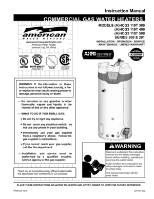
 COMMERCIAL GAS WATER HEATERS
Instruction Manual
PRINTED 1215  327737-002
PLACE THESE INSTRUCTIONS ADJACENT TO HEATER AND NOTIFY OWNER TO KEEP FOR FUTURE REFERENCE.
Thank you for buying this energy efficient water heater.
We appreciate your confidence in our products.
Read and understand this instruction
manual and the safety messages
herein before installing, operating or
servicing this water heater .
Failure to follow these instructions and
safety messages could result in death
or serious injury.
This...
Page 2
2
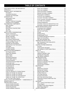
Power Vent Installation....................................................... 23
Direct Vent Installation  ....................................................... 23
Vertical Termination Installation  .......................................... 24
Sidewall Termination Installation  ........................................ 26
Polypropylene Installations  ................................................ 27
AL29-4C® Vent Installations  .............................................. 28
Concentric...
Page 3
3
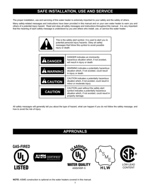
SAFE INSTALLATION, USE AND SERVICE
The proper installation, use and servicing of this water heater is extremely important to your safety and the safety of others.
Many safety-related messages and instructions have been provided in this manual and on your own water heater to warn you and
others of a potential injury hazard.  Read and obey all safety messages and instructions throughout this manual.  It is very important
that the meaning of each safety message is understood by you and others who...
Page 4
4
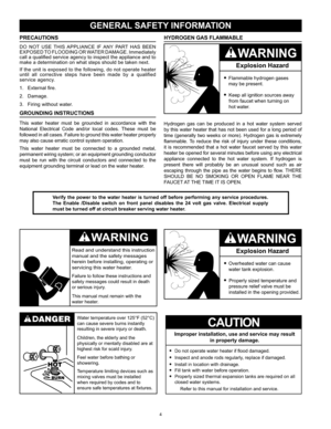
PRECAUTIONS
DO  NOT  USE  THIS  APPLIANCE  IF  ANY  PART  HAS  BEEN
EXPOSED TO FLOODING OR WATER DAMAGE. Immediately
call a qualified service agency to inspect the appliance and to
make a determination on what steps should be taken next.
If the unit is exposed to the following, do not operate heater
until  all  corrective  steps  have  been  made  by  a  qualified
service agency.
1. External fire.
2.  Damage.
3.  Firing without water.
GROUNDING INSTRUCTIONS
This  water  heater  must  be  grounded...
Page 5
5
GENERAL SAFETY INFORMATION
Fire or Explosion Hazard
Read instruction manual befor e
installing, using or servicing water heater .
Avoid all ignition sources if you smell gas .
Do not store or use gasoline or other flammable vapors and
liquids in the vicinity of this or any other appliance.
Use only the gas shown on the water heater rating label.
Keep ignition sources away from faucets after extended
periods of non-use. Maintain required clearances to combustibles. Do not expose water heater controls to...
Page 6
6
Thank  You  for  purchasing  this  water  heater.  Properly  installed
and maintained, it should give you years of trouble free service.
ABBREVIATIONS USED
Abbreviations found in this Instruction Manual include :•  ANSI - American National Standards Institute
•  ASME - American Society of Mechanical Engineers
•  AHRI - Air Conditioning, Heating and Refrigeration Institute
•  NEC - National Electrical Code
•  NFPA - National Fire Protection Association
•  UL - Underwriters Laboratory
•  CSA - Canadian...
Page 7
7
BASIC OPERATION
The  water  heaters  covered  in  this  manual  have  a  helical  coil
shaped  heat  exchanger  that  is  submerged  in  the  storage  tank.
The  water  heater’s  Main  Burner  is  a  radial  design  burner,  it
is  mounted  on  the  top  and  fires  downward  through  the  heat
exchanger.  This  is  a  forced  draft  burner;  hot  burning  gases  are
forced  through  the  heat  exchanger  under  pressure  and  exit
through the exhaust/vent connection located at the bottom of the...
Page 8
8
gas  pressure  is  above  minimum  requirements.  The  control
system monitors this switch and will disable heating operation
if  its  contacts  are  open  during  a  heating  cycle.  See  Table  4
and the Gas Pressure Requirements on page 10.
10.  Blower  Prover  switch.  Normally  open  contacts  that  close  on  a
rise  in  pressure.  This  switch  is  used  to  insure  the  Combustion
Blower  is  operating  properly.  The  control  system  monitors  this
switch and will disable heating...
Page 9
9
circuit board, the control system’s LCD display and operational
buttons.  Used  to  adjust  various  user  settings  and  view
operational  information.  See  Control  System  Operation  on
page 44.
11.  Temperature-Pressure  Relief  Valve.  See  Temperature-
Pressure Relief Valve on page 15.
12.  Temperature-Pressure Relief Valve discharge pipe - see T&P
Valve Discharge Pipe Requirements: on page 15.
13.  Lower  Temperature  Probe,  1  of  2  temperature  probes.  The
water  heater’s  control...
Page 10
10
GAS
INTAKE
CLEANOU TT&PDRAI N
EXHAUS T
1 1/2 NPT
WATER
OUTLET
FRONT 18° 30° 45° 42°
70°20°
TOPRECIRC RETURN
CLEANOUT 3/4 NPT
T&P
3/4 NPT DRAIN
1 1/2 NPT
WATER INLET 4 EXHAUST VENT
CONNECTION
 52
in132.08c m
32.39cm12-3 /4in4- 3/4in12.07cm
58.43cm23 in
 75 -3/4in192.41c m
FRONT
CONNECTION
1 1/2 SUPPLY GAS
BACK4 PVC AIR INTAKE
CONNECTION
73-3/4in
33 -1/8 in187.3cm
84.12cm  O.D.
69
-1/4 in175.9cm
63
-1/8 in160.35cm
WATER
OUTLET
HEIGHT
Figure 6
These designs comply with the current edition of the...


