Acer Aspire 5534 Service Guide
Here you can view all the pages of manual Acer Aspire 5534 Service Guide. The Acer manuals for Notebook are available online for free. You can easily download all the documents as PDF.
Page 131
Chapter 3121
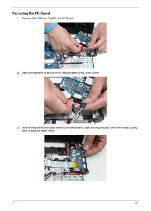
Replacing the I/O Board
1.Connect the I/O Board Cable to the I/O Board.
2.Apply the adhesive to secure the I/O Board cable to the Lower Cover.
3.Insert the board into the lower cover so the white tab is under the securing clip in the lower cover, taking
care to align the screw holes.
Page 132
122Chapter 3
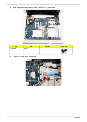
4.Insert the single screw to secure the I/O Board to the Lower Cover.
5.Connect the cable to the Mainboard.
StepSizeQuantityScrew Type
I/O Board M2.5*6 1
Page 133
Chapter 3123
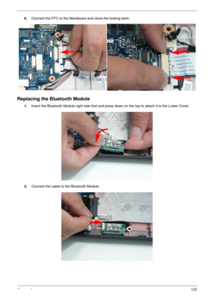
6.Connect the FFC to the Mainboard and close the locking latch.
Replacing the Bluetooth Module
1.Insert the Bluetooth Module right side first and press down on the top to attach it to the Lower Cover.
2.Connect the cable to the Bluetooth Module.
Page 134
124Chapter 3
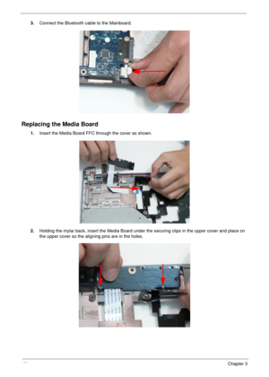
3.Connect the Bluetooth cable to the Mainboard.
Replacing the Media Board
1.Insert the Media Board FFC through the cover as shown.
2.Holding the mylar back, insert the Media Board under the securing clips in the upper cover and place on
the upper cover so the aligning pins are in the holes.
Page 135
Chapter 3125
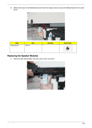
3.Adhere the mylar to the Media Board and insert the single screw to secure the Media Board to the Lower
Cover.
Replacing the Speaker Modules
1.Place the right side speaker onto the Lower Cover as shown.
StepSizeQuantityScrew Type
Media Board M2.5*3 1
Page 136
126Chapter 3
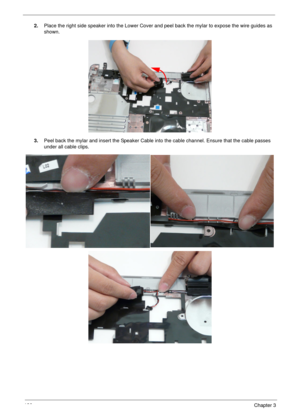
2.Place the right side speaker into the Lower Cover and peel back the mylar to expose the wire guides as
shown.
3.Peel back the mylar and insert the Speaker Cable into the cable channel. Ensure that the cable passes
under all cable clips.
Page 137
Chapter 3127
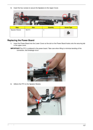
4.Insert the four screws to secure the Speakers to the Upper Cover.
Replacing the Power Board
1.Insert the Power Board into the Lower Cover so the slot on the Power Board hooks onto the securing tab
in the upper cover.
IMPORTANT:The FFC is soldered to the power board. Take care when lifting to minimize bending of the
connection, lest breakage occur.
2.Adhere the FFC to the Speaker Module.
StepSizeQuantityScrew Type
Speaker Module M2.5*3 4
Page 138
128Chapter 3
3.Insert the single screw to secure the Power Board to the Lower Cover.
Replacing the Touchpad Bracket
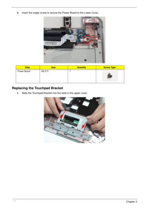
1.Slide the Touchpad Bracket into the slots in the upper cover.
StepSizeQuantityScrew Type
Power Board M2.5*3 1
Page 139
Chapter 3129
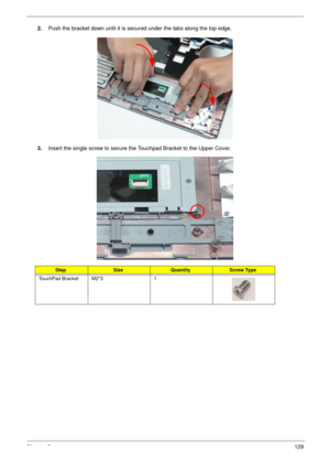
2.Push the bracket down until it is secured under the tabs along the top edge.
3.Insert the single screw to secure the Touchpad Bracket to the Upper Cover.
StepSizeQuantityScrew Type
TouchPad Bracket M2*3 1
Page 140
130Chapter 3
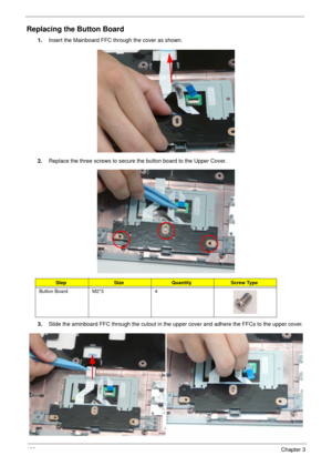
Replacing the Button Board
1.Insert the Mainboard FFC through the cover as shown.
2.Replace the three screws to secure the button board to the Upper Cover.
3.Slide the aminboard FFC through the cutout in the upper cover and adhere the FFCs to the upper cover.
StepSizeQuantityScrew Type
Button Board M2*3 4
