Acer Aspire 5534 Service Guide
Here you can view all the pages of manual Acer Aspire 5534 Service Guide. The Acer manuals for Notebook are available online for free. You can easily download all the documents as PDF.
Page 111
Chapter 3101
Removing the Antennas
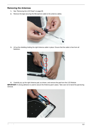
1.See “Removing the LCD Panel” on page 95.
2.Remove the tape securing the Microphone cable to the antenna cables.
3.Lift up the shielding holding the right Antenna cable in place. Ensure that the cable is free from all
fasteners.
4.Carefully pry up the right Antenna pad, as shown, and remove the pad from the LCD Module.
IMPORTANT: A strong adhesive is used to secure the Antenna pad in place. Take care not to bend the pad during
removal.
Page 112
102Chapter 3
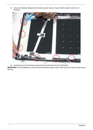
5.Lift up the shielding holding the left Antenna cable in place. Ensure that the cable is free from all
fasteners.
6.Carefully pry up the left Antenna pad and remove the pad from the LCD Module.
IMPORTANT: A strong adhesive is used to secure the Antenna pad in place. Take care not to bend the pad during
removal.
Page 113
Chapter 3103
LCD Module Reassembly Procedure
Replacing the Antennas
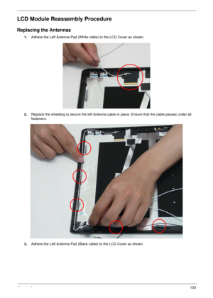
1.Adhere the Left Antenna Pad (White cable) to the LCD Cover as shown.
2.Replace the shielding to secure the left Antenna cable in place. Ensure that the cable passes under all
fasteners.
3.Adhere the Left Antenna Pad (Black cable) to the LCD Cover as shown.
Page 114
104Chapter 3
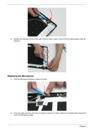
4.Replace the shielding to secure the right Antenna cable in place. Ensure that the cable passes under all
fasteners.
Replacing the Microphone
1.Push the Microphone Module in place as shown.
2.Press the cable onto the LCD cover as shown to secure it in place. Adhere the shielding tabs where they
cover the Microphone cable.
Page 115
Chapter 3105
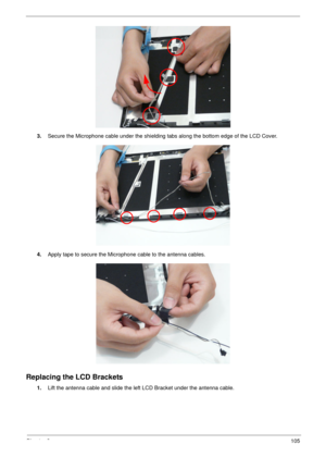
3.Secure the Microphone cable under the shielding tabs along the bottom edge of the LCD Cover.
4.Apply tape to secure the Microphone cable to the antenna cables.
Replacing the LCD Brackets
1.Lift the antenna cable and slide the left LCD Bracket under the antenna cable.
Page 116
106Chapter 3
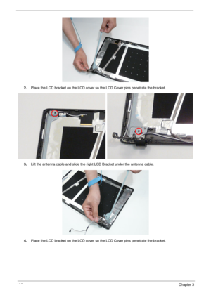
2.Place the LCD bracket on the LCD cover so the LCD Cover pins penetrate the bracket.
3.Lift the antenna cable and slide the right LCD Bracket under the antenna cable.
4.Place the LCD bracket on the LCD cover so the LCD Cover pins penetrate the bracket.
Page 117
Chapter 3107
Replacing the FPC Cable
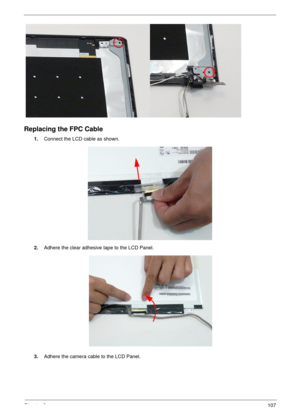
1.Connect the LCD cable as shown.
2.Adhere the clear adhesive tape to the LCD Panel.
3.Adhere the camera cable to the LCD Panel.
Page 118
108Chapter 3
Replacing the LCD Panel
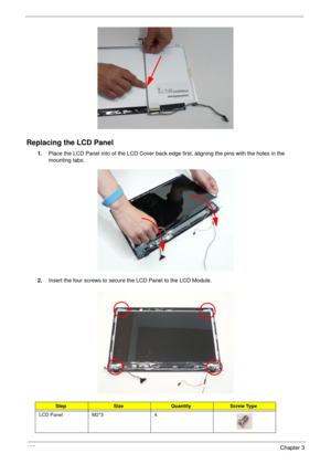
1.Place the LCD Panel into of the LCD Cover back edge first, aligning the pins with the holes in the
mounting tabs.
2.Insert the four screws to secure the LCD Panel to the LCD Module.
StepSizeQuantityScrew Type
LCD Panel M2*3 4
Page 119
Chapter 3109
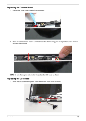
Replacing the Camera Board
1.Connect the cable to the Camera Board as shown.
2.Place the Camera Board into the LCD Module so that the mounting pins are aligned and press down to
secure to the adhesive.
NOTE: Be sure the magnet rests next to the post on the LCD cover as shown.
Replacing the LCD Bezel
1.Route the LVDS cable through the cable channel and hinge cover as shown.
Page 120
11 0Chapter 3
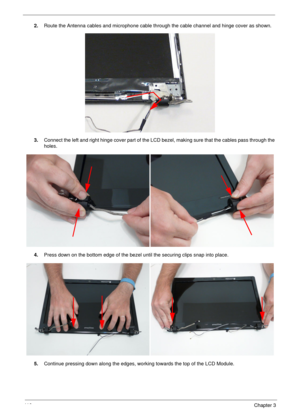
2.Route the Antenna cables and microphone cable through the cable channel and hinge cover as shown.
3.Connect the left and right hinge cover part of the LCD bezel, making sure that the cables pass through the
holes.
4.Press down on the bottom edge of the bezel until the securing clips snap into place.
5.Continue pressing down along the edges, working towards the top of the LCD Module.
