Honeywell Taz3 Manual
Here you can view all the pages of manual Honeywell Taz3 Manual. The Honeywell manuals for Control panel are available online for free. You can easily download all the documents as PDF.
Page 1
PRODUCT DATA
68- 0223-2® U.S. Registered Trademark
Copyright © 2001 Honeywell   All Rights Reserved
TZ-3 TotalZone® Zone Control Panel
APPLICATION
The TZ-3 TotalZone Zone Control Panel controls single-stage,
multi-sta
ge, conventional or heat pump heat/cool equipment.
It controls 2 or 3 zones, and is expandable up to 30 zones with
optional TotalZone® Add-A-Zone™ Zone Control Panel.
FEATURES
• Up to three stages heat and two stages cooling can be
controlled by thermostat or built-in timer, based on...
Page 2
TZ-3 TOTALZONE® ZONE CONTROL PANEL
68-0223-2 2
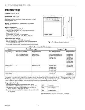
SPECIFICATIONS
Electrical:
24 Vac, 60 Hz.
Dimensions:
See Fi
g. 1.
Mounting:
Mounts with three screws
(provided) through
holes in cabinet back
Wiring:
18-
gauge wire for all equipment and system
connections
Wiring Connections:
Thermostat: W2, L, G, Y, R, W
Dam
pers: M6 (Closed); M4 (Open); M1 (Common)
ZoneMax TL, TL
Zone-A-Lone: OC,OC.
Transformer: TR1
(hot), TR2 (common).
E
quipment: Y2, Y1, O, R, G, B, W1, E, W2, W3.
Thermostats (See Table...
Page 3
TZ-3 TOTALZONE® ZONE CONTROL PANEL
3 68-0223-2
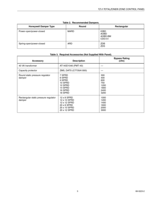
Table 2.  Recommended Dampers.
Table 3.  Required Accessories (Not Supplied With Panel). Honeywell Damper Type Round Rectangular
Power-open/power-closedMARDIOBD
AOBD
AOBD-BM
CDO-51
Spring-open/power-closedARDZDB
ZDS
Accessory DescriptionBypass Rating
(cfm)
40 VA transformerAT140D1046 (PMT-40)—
Capacity protectorZMS, DATS (C7735A1000)—
Round static pressure regulator
dam
per
7 SPRD
8 SPRD
9 SPRD
10 SPRD
12 SPRD
14 SPRD
16 SPRD
18 SPRD300
400
600
750
1200...
Page 4
TZ-3 TOTALZONE® ZONE CONTROL PANEL
68-0223-2 4
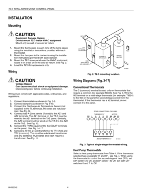
INSTALLATION
Mounting
CAUTION
Equipment Damage Hazard.
Do not mount TZ-3 inside HVAC equipment
Mount onl
y on wall or on cold air return
1.
Mount the thermostats in each zone of the livin
g space
usin
g the installation instructions provided with each
thermostat.
2.
Mount the dam
pers in the ductwork using the installa-
tion instructions
provided with each damper.
3.
Mount the TZ-3 zone panel near the HVAC equipment;
locate it on a wall or on the...
Page 5
TZ-3 TOTALZONE® ZONE CONTROL PANEL
5 68-0223-2
Fig. 4. Heat pump thermostat with separate Y1 and W1
terminals and multi-stage thermostat wiring.
If the thermostat selected has a sin
gle Y terminal, see Fig. 5.
Select a sin
gle Y thermostat for each zone. See Table 1.
Set DIP switch 6 or 7
(not both) to the On position. Set switch
6 to On when B on the thermostat is wired to W on the
panel.
Set switch 7 to On when 0 on the thermostat is wired to W on
the
panel.
When usin
g the zone thermostat to...
Page 6
TZ-3 TOTALZONE® ZONE CONTROL PANEL
68-0223-2 6
Fig. 9. MARD and CDO-51 Damper wiring.
ML6161 Motor Actuator
When the ML6161 Motor Actuator is used, wire as shown in
Fig. 10. Wire the R8222 relay to prevent the damper LED from
constantl
y lighting amber.
Fig. 10. ML6161 Damper Motor Actuator wiring.
Transformer
Wire the transformer to the panel as shown in Fig. 11.
NOTE: If the installation includes an Add-A-Zone
panel, see
the TotalZone Add-A-Zone Panels section.
Fig. 11. Transformer wiring....
Page 7
TZ-3 TOTALZONE® ZONE CONTROL PANEL
7 68-0223-2
Multi-Stage: Wire the equipment as shown in Fig. 14 using the
W2 terminal for second stage of heat and the W3 terminal for
third sta
ge of heat. Wire the Y2 for second stage of cooling.
Fig. 14. Heating and cooling equipment.
Heat Pump Equipment
Wire the heat pump to the equipment terminals on the panel
as shown in Fi
g. 15. Refer to manufacturer’s instructions for
additional wiring instructions and substitute the TZ-3
equipment terminals for the...
Page 8
TZ-3 TOTALZONE® ZONE CONTROL PANEL
68-0223-2 8
Fig. 15. Heat pump with auxiliary heat wiring.
.
Fig. 16. Trane XL 1800 with TAYPLUS 103 in restricted mode wiring.
Water Source Heat Pumps
Wire the equipment, as applicable, to the TZ-3 as shown in Fi
g. 17. Turn DIP switch number 8 to On for fan on in heat.
Remove the two-sta
ge emergency heat jumper.
W2
W3
M19075
E W1
W2E
B G
R
24V TRANSFORMER
FAN RELAYREVERSING
VALVE (COOL)
EMERGENCY
HEATING RELAY
2 STAGE
HEATING RELAY
HEAT PUMP CONTROLSTZ-3
PA N E L...
Page 9
TZ-3 TOTALZONE® ZONE CONTROL PANEL
9 68-0223-2
Waterfurnace: Wire this system to the panel as shown in Fig.
17 except use two isolation relays on compressor wires W1,
Y1 and  W2, Y2.
Fig. 17. Water source heat pump wiring.
STARTUP AND CHECKOUT
After the installation is complete, verify correct operation as
follows:
1.
Place the Em Heat switch in the Off
(down) position.
2.
Place the Zone-A-Lone switch in the Occup/Remote (up) position.
3.
Ver i f
y that the DIP switches are set correctly. See...
Page 10
TZ-3 TOTALZONE® ZONE CONTROL PANEL
68-0223-2 10
OPERATION
Sequence of Operation
On a call for heating or cooling, the zone damper stays open
to the calling zone, and the dampers close to the zones that
are not callin
g. The TZ-3 panel brings on the heating or
cooling and conditioned air is delivered to the calling zone
until that zone is satisfied. When the call is satisfied, the
s
ystem enters the Purge mode. This holds open the damper
of the last zone calling and purges into that zone. The purge...


