AEM Water Methanol Failsafe Device 303020M User Manual
Here you can view all the pages of manual AEM Water Methanol Failsafe Device 303020M User Manual. The AEM manuals for Analog Performance Gauges are available online for free. You can easily download all the documents as PDF.
Page 1
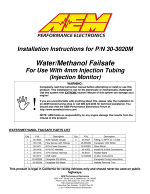
AEM Performance Electronics 2205 126th Street Unit A, Hawthorne, CA. 90250 Phone: (310) 484-2322 Fax: (310) 484-0152 http://www.aemelectronics.com Instruction Part Number: 10-3020 Rev 02 2011 AEM Performance Electronics Installation Instructions for P/N 30-3020M Water/Methanol Failsafe For Use With 4mm Injection Tubing (Injection Monitor) WATER/METHANOL FAILSAFE PARTS LIST This product is legal in California for racing vehicles only and should never be used on...
Page 2
Page 2
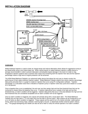
INSTALLATION DIAGRAM

OVERVIEW

Water/methanol injection is used to lower air charge temps and reduce detonation which allows for aggressive tuning to
be utilized while using a low octane base fuel.  When relying heavily on water/methanol injection a safety device is
strongly recommended in order to prevent detonation and possible engine damage in the event of a leak or clog.
Progressive injection systems have a dynamic flow output and monitoring both the injection flow rate and the...
Page 3
Page 3
The Water/Methanol Failsafe also has an auxiliary input that can be used to trigger an alarm condition.  Users with the
AEM W ater/Methanol Injection System (PN 30-3000 & 30-3001) can use the “Boost Safe” ground output to trigger the
auxiliary input if any of the internal fault conditions are detected by the AEM progressive controller.

NOTE: It is HIGHLY recommended that the Water/Methanol Failsafe be used in conjunction with the AEM
Water/Methanol Injection Filter (AEM part# 30-3003)....
Page 4
Page 4
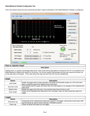
Water/Methanol Failsafe Configuration Tab

This is the section where the flow monitoring and alarm output functionality of the Water/Methanol Failsafe is configured.


Flow vs. Injection Graph
Description
Displays flow vs. injection percentage data points. Flow points will be populated live whenever the PC is connected to the
Water/Methanol Failsafe and injection is occurring. The current injection percentage and flow rate values are shown live
on the right side of the graph.  This...
Page 5
Page 5


Alarm Configuration
Option Description
Aux Input Status Shows the status of the auxiliary alarm input; on or off
Alarm Delay  Period of time that measured flow can be outside the upper and low flow limit lines before an
alarm condition is triggered; 100-1000 milliseconds
Alarm Reset Period of time flow must be within the acceptable range before the alarm will automatically reset;
1-10 seconds
Disable Auto Reset Select to require power cycle to reset alarm; overrides the...
Page 6
Page 6
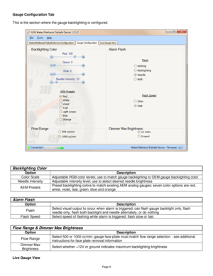
Gauge Configuration Tab

This is the section where the gauge backlighting is configured.


Live Gauge View
Backlighting Color
Option Description
Color Scale Adjustable RGB color levels; use to match gauge backlighting to OEM gauge backlighting color
Needle Intensity Adjustable intensity level; use to select desired needle brightness
AEM Presets Preset backlighting colors to match existing AEM analog gauges; seven color options are red,
white, violet, teal, green, blue and...
Page 7
Page 7

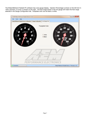
The Water/Methanol Failsafe PC software has a live gauge display.  Injection Percentage is shown on the left from 0-
100% and flow, in cc/min, is shown on the right.  The flow range shown in the live gauge will match the flow range
selected in the Gauge Configuration tab.  Faceplate color can be black or white.
Page 8
Page 8
WATER/METHANOL FAILSAFE CONFIGURATION

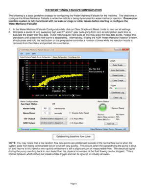
The following is a basic guideline strategy for configuring the Water/Methanol Failsafe for the first time.  The ideal time to
configure the Water/Methanol Failsafe is while the vehicle is being dyno tuned for water/methanol injection.  Ensure your
injection system is fully functional with no leaks or clogs or other issues before starting to configure the
Water/Methanol Failsafe!

1. In the W ater/Methanol Failsafe Configuration tab, click on Clear...
Page 9
Page 9
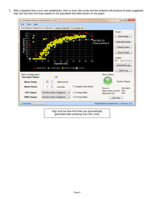
3. With a baseline flow curve now established, click on Auto Set Limits and the software will produce its best suggested
high and low flow limit lines based on the populated flow data shown on the graph.


High and low flow limit lines are automatically
generated after pressing Auto Set Limits
Page 10
Page 10
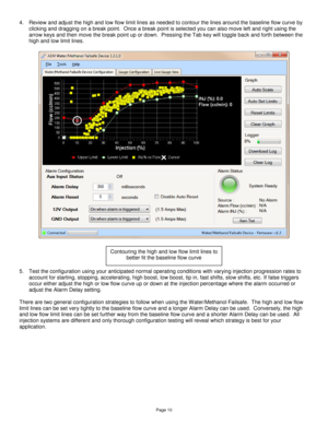
4. Review and adjust the high and low flow limit lines as needed to contour the lines around the baseline flow curve by
clicking and dragging on a break point.  Once a break point is selected you can also move left and right using the
arrow keys and then move the break point up or down.  Pressing the Tab key will toggle back and forth between the
high and low limit lines.


5. Test the configuration using your anticipated normal operating conditions with varying injection...
