AEM Analog H2O Flow Gauge 305141 User Manual
Here you can view all the pages of manual AEM Analog H2O Flow Gauge 305141 User Manual. The AEM manuals for Analog Performance Gauges are available online for free. You can easily download all the documents as PDF.
Page 1
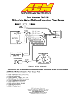
AEM Performance Electronics 2205 126th Street Unit A, Hawthorne, CA. 90250 Phone: (310) 484-2322 Fax: (310) 484-0152 http://www.aempower.com Instruction Part Number: 10-5141 Rev 01 2009 AEM Performance Electronics Part Number 30-5141 500 cc/min Water/Methanol Injection Flow Gauge Figure 1. Wiring Schematic AEM Water/Methanol Injection Flow Gauge Parts 1 x 35-5141(B/W) Flow Gauge Assembly 1 x 35-2128 Flow Sensor 2 x 35-4527 Fittings, ¼ NPTF to ¼ Tube 1 x 35-4302 Install Kit (6...
Page 2
Page 2
INSTALLATION

1. Disconnect the negative battery cable.
2. Secure the gauge in a 2 1/16” (52MM) mounting hole with the supplied bracket.  Use
the supplied rubber band as a spacer around the gauge if it fits loosely into its
mounting hole.
3. Plug the 8-wire power harness into the mating connector on the back of the gauge
and connect the wires as shown in Figure 1.  The power harness connector can only
be inserted one way.
4. Install flow sensor as close as practically possible to final...
Page 3
Page 3
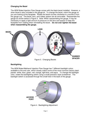
Changing the Bezel

The AEM Water/Injection Flow Gauge comes with the black bezel installed.  However, a
silver bezel is also included in the gauge kit.  To change the bezel, orient the gauge so
you are looking at the faceplate.  Rotate the bezel counter-clockwise to unscrew it from
the gauge cup.  The bezel, lens, and rubber spacer are all removable.  Reassemble the
gauge as shown below in Figure 3.  Note: When reassembling the gauge, it may be
necessary to apply a light amount of...
Page 4
Page 4

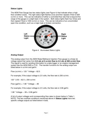
Status Lights

The AEM Flow Gauge has two status lights (see Figure 4) that indicate when a high
flow condition exists.  The right status light flashes once and then repeats if flow is 625
cc/min or more.  This can be indicative of either a controlled flow rate that is beyond the
range of the gauge or a slight leak in the system.  Both status lights flash four times and
then repeat if flow is 1000 cc/min or more.  This can be indicative of an uncontrolled
open line condition, such as a...
Page 5
Page 5

Voltage cc/min gal/hr
0.50 0 0.00
0.75 31 0.50
1.00 63 0.99
1.25 94 1.49
1.50 125 1.98
1.75 156 2.48
2.00 188 2.97
2.25 219 3.47
2.50 250 3.96
2.75 281 4.46
3.00 313 4.95
3.25 344 5.45
3.50 375 5.94
3.75 406 6.44
4.00 438 6.93
4.25 469 7.43
4.50 500 7.93
4.65 625 9.91
4.85 1000 15.85


Connector Pinouts

The pinouts for the 3-pin sensor harness and 8-pin power harness are provided below
in Figure 6.


Figure 6.  Harness...
Page 6
Page 6

Specifications

Gauge
Supply Current 0.1 A
Differential Analog Outputs 1
Measuring Range 0-500 cc/min
0-7.93 gal/hr
Operating Voltage (nominal) 8.5-15 volts dc
Harness & Connector Temp Limit: 105C

Notes

The sensor is a precision pressure measuring device and should not be subject to
mechanical or thermal shock or it may be damaged.

If  further  tuning  help  is  needed  be  sure  to  visit  the  video  gallery  or  performance
electronics  forum  at www.aempower.com for...
Page 7
Page 7
12 MONTH LIMITED WARRANTY

Advanced  Engine Management  Inc.  warrants  to  the  consumer  that  all  AEM  High
Performance  products  will  be  free  from  defects  in  material  and  workmanship  for  a
period of twelve (12) months from date of the original purchase. Products that fail within
this  12-month  warranty  period  will  be  repaired  or  replaced  at  AEM’s  option,  when
determined  by  AEM  that  the  product  failed  due  to  defects  in  material  or  workmanship.
This...


