AEM Analog EGT SAE Gauge 305131 User Manual
Here you can view all the pages of manual AEM Analog EGT SAE Gauge 305131 User Manual. The AEM manuals for Analog Performance Gauges are available online for free. You can easily download all the documents as PDF.
Page 1
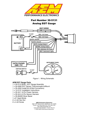
AEM Performance Electronics 2205 126th Street Unit A, Hawthorne, CA. 90250 Phone: (310) 484-2322 Fax: (310) 484-0152 http://www.aempower.com Instruction Part Number: 10-5131 Rev 04 2009 AEM Performance Electronics Part Number 30-5131 Analog EGT Gauge Figure 1. Wiring Schematic AEM EGT Gauge Parts 1 x 35-5131(B/W) EGT Gauge Assembly 1 x 30-2065 EGT Sensor Thermocouple w/Mount 1 x 35-4302 Install Kit (6 Butt Connectors) 1 x 10-5131 Installation Instructions 1 x 35-3411 8-Pin Power...
Page 2
Page 2
INSTALLATION

1. Disconnect the negative battery cable.
2. Secure the gauge in a 2 1/16th” (52MM) mounting hole with the supplied bracket.
3. Plug the 8-wire power harness into the mating connector on the back of the
gauge and connect the wires as shown in Figure 1.  Note: the locating tabs on
the side of the connector should be nearest the center of the gauge.
4. Connect the sensor cable to the gauge.  The locating tabs should be closest to
the center of the gauge.
5. Mount the...
Page 3
Page 3
 Thermocouple Mounting

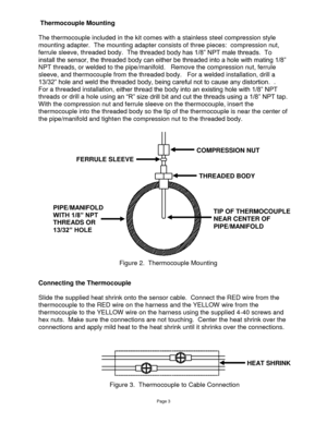
The thermocouple included in the kit comes with a stainless steel compression style
mounting adapter.  The mounting adapter consists of three pieces:  compression nut,
ferrule sleeve, threaded body.  The threaded body has 1/8” NPT male threads.  To
install the sensor, the threaded body can either be threaded into a hole with mating 1/8”
NPT threads, or welded to the pipe/manifold.   Remove the compression nut, ferrule
sleeve, and thermocouple from the threaded body....
Page 4
Page 4

Changing the Bezel

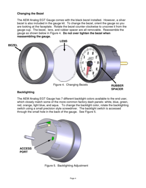
The AEM Analog EGT Gauge comes with the black bezel installed.  However, a silver
bezel is also included in the gauge kit.  To change the bezel, orient the gauge so you
are looking at the faceplate.  Rotate the bezel counter-clockwise to unscrew it from the
gauge cup.  The bezel,  lens, and rubber spacer are all removable.  Reassemble the
gauge as shown below in Figure 4.  Do not over tighten the bezel when
reassembling the gauge....
Page 5
Page 5
Status Lights

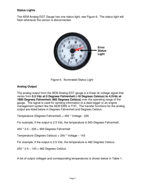
The AEM Analog EGT Gauge has one status light, see Figure 6.  The status light will
flash whenever the sensor is disconnected.


Analog Output

The analog output from the AEM Analog EGT gauge is a linear dc voltage signal that
varies from 0.5 Vdc at 0 Degrees Fahrenheit (-18 Degrees Celsius) to 4.5Vdc at
1800 Degrees Fahrenheit (982 Degrees Celsius) over the operating range of the
gauge.  The signal is used for sending information to a data logger or an engine...
Page 6
Page 6
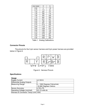
VOLTAGE °F °C
0.50 0 -18
0.75 113 45
1.00 225 107
1.25 338 170
1.50 450 232
1.75 563 295
2.00 675 357
2.25 788 420
2.50 900 482
2.75 1013 545
3.00 1125 607
3.25 1238 670
3.50 1350 732
3.75 1463 795
4.00 1575 857
4.25 1688 920
4.50 1800 982


Connector Pinouts

 The pinouts for the 3-pin sensor harness and 8 pin power harness are provided
below in Figure 6.


Specifications

Gauge
Supply Current
Page 7
Page 7

NOTES:
If  further  tuning  help  is  needed  be  sure  to  visit  the  video  gallery or  performance  electronics
forum at www.aempower.com for comprehensive instructional videos and information.


Replacement EGT Gauge Components

30-2065 K-Type Thermocouple with Bung
35-3411 8-Pin Power Harness
35-3414 3-Pin Sensor Harness

12 MONTH LIMITED WARRANTY  Advanced Engine Management Inc. warrants to the consumer that all AEM High Performance products will  be free from defects in...
