Home
>
AEM
>
Analog Performance Gauges
>
AEM Analog Boost Fuel Pressure SAE Gauge 305144 User Manual
AEM Analog Boost Fuel Pressure SAE Gauge 305144 User Manual
Here you can view all the pages of manual AEM Analog Boost Fuel Pressure SAE Gauge 305144 User Manual. The AEM manuals for Analog Performance Gauges are available online for free. You can easily download all the documents as PDF.
Page 1
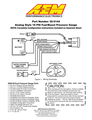
AEM Performance Electronics 2205 126th Street Unit A, Hawthorne, CA. 90250 Phone: (310) 484-2322 Fax: (310) 484-0152 http://www.aemelectronics.com Instruction Part Number: 10-5144 Rev 01 2010 AEM Performance Electronics Part Number 30-5144 Analog Style 15 PSI Fuel/Boost Pressure Gauge NOTE: Faceplate Configuration Instructions Included on Separate Sheet Figure 1. Wiring Schematic AEM Oil/Fuel Pressure Gauge Parts 1 x 35-5144 Pressure Gauge Assembly 1 x 30-2131-15 PSIG Pressure...
Page 2
Page 2
INSTALLATION

1. Disconnect the negative battery cable.
2. Secure the gauge in a 2 1/16th” (52MM) mounting hole with the supplied bracket.
3. Plug the 8-wire power harness into the mating connector on the back of the
gauge and connect the wires as shown in Figure 1.  Note: the locating tabs on
the side of the connector should be nearest the center of the gauge.
4. To measure fuel pressure, thread the sensor into a suitable pressure port that
has 1/8” NPT female threads.  Note: a small...
Page 3
Page 3
 BROWN – The BROWN wire should be connected to the Analog – input.  If the
EMS or similar device does not have a – input, the BROWN wire should be connected
to a sensor ground.  If no sensor ground is available, the BROWN wire should be
connected to a power ground.  Note: The BROWN wire must be connected in order
to get correct readings from the analog output.
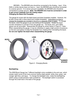
Changing the Bezel and Faceplate

The gauge kit comes with the black bezel and black faceplate installed.  However, the
kit also...
Page 4
Page 4


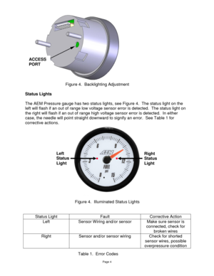
Status Lights

The AEM Pressure gauge has two status lights, see Figure 4.  The status light on the
left will flash if an out of range low voltage sensor error is detected.  The status light on
the right will flash if an out of range high voltage sensor error is detected.  In either
case, the needle will point straight downward to signify an error.  See Table 1 for
corrective actions.


Status Light Fault Corrective Action
Left Sensor Wiring and/or sensor Make sure sensor is...
Page 5
Page 5
Analog Output

The analog output from the AEM 100 PSI Pressure gauge is a linear dc voltage signal
that varies from 0.5 Vdc at 0 psig (0 Bar) to 4.5 Vdc at 15 psig (1 Bar) over the
operating range of the gauge.  The signal is used for sending information to a data
logger or an engine management system like the AEM EMS or F/IC.  The transfer
function for pressure units in PSI is listed below.

Pressure (psi) = 3.75 x Voltage – 1.88

The transfer function for pressure units in bar is...
Page 6
Page 6
3-pin sensor harness
Red - 5V sensor power
Black - Sensor ground
Green - Sensor signal
8-pin power harness
Red – 12V Power
Black – Power ground
Pink – Switched 12V power
White – Analog output
Brown – Analog ground
Grey – Lighting intensity


Specifications

Gauge
Supply Current 0.1 A
Differential Analog Outputs 1
Measuring Range 0 PSI – 15 PSI
0 Bar to 1 Bar
Operating Voltage (nominal) 8.5-15 volts dc
Harness & Connector Temp Limit: 105C

Notes

The sensor is a...
Page 7
Page 7
12 MONTH LIMITED WARRANTY  Advanced Engine Management Inc. warrants to the consumer that all AEM High Performance products will  be free from defects in material  and  workmanship  for  a  period  of  twelve  (12)  months  from  date  of  the  original  purchase.  Products  that  fail  within  this  12-month warranty period will be repaired or replaced at AEM’s option, when determined by AEM that the product failed due to defects in  material  or  workmanship.  This  warranty  is  limited  to...


