Acer Aspire 4715z 4315 User Manual
Here you can view all the pages of manual Acer Aspire 4715z 4315 User Manual. The Acer manuals for Notebook are available online for free. You can easily download all the documents as PDF.
Page 51
Chapter 241
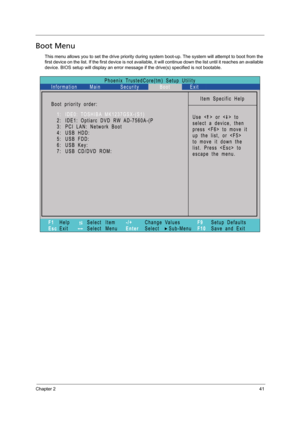
Boot Menu
This menu allows you to set the drive priority during system boot-up. The system will attempt to boot from the
first device on the list. If the first device is not available, it will continue down the list until it reaches an available
device. BIOS setup will display an error message if the drive(s) specified is not bootable.
Page 52
42Chapter 2
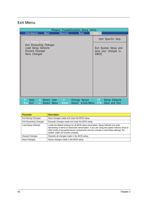
Exit Menu
ParameterDescription
Exit Saving Changes Save changes made and close the BIOS setup.
Exit Discarding Changes Discards changes made and close the BIOS setup.
Load Setup Defaults Loads the default settings for all BIOS setup parameters. Setup Defaults are quite
demanding in terms of resources consumption. If you are using low-speed memory chips or
other kinds of low-performance components and you choose to load these settings, the
system might not function properly.
Discard Changes...
Page 53
Chapter 243
BIOS Recovery
If BIOS flash procedure fails in your system, perform a BIOS recovery procedure by using the crisis recovery
diskette. During this procedure, the system will force BIOS to load and execute a special BIOS block (also
called boot block) to restore the BIOS code from the crisis recovery diskette.
Note the following when restoring the BIOS settings:
TUse the  +  hotkey to enable BIOS recovery during BIOS POST.
Important: When using the  +  hotkey to enable BIOS recovery, we...
Page 55
Chapter 345
This chapter contains step-by-step procedures on how to disassemble the notebook computer for
maintenance and troubleshooting.
Disassembly Requirements
To disassemble the computer, you need the following tools:
TWrist grounding strap and conductive mat for preventing electrostatic discharge
TFlat-blade screwdriver
TPhilips screwdriver
THex screwdriver
TPlastic flat-blade screwdriver
TPlastic tweezers
NOTE: The screws for the different components vary in size. During the disassembly process,...
Page 56
46Chapter 3
General Information
Pre-disassembly Instructions
Before proceeding with the disassembly procedure, make sure that you do the following:
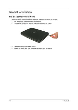
1.Turn off the power to the system and all peripherals.
2.Unplug the AC adapter and all power and signal cables from the system.
3.Place the system on a flat, stable surface.
4.Remove the battery pack.  See “Removing the Battery Pack” on page 49.
Page 57
Chapter 347
Disassembly Process
The disassembly process is divided into the following stages:
TExternal module disassembly
TMain unit disassembly
TLCD module disassembly
The flowcharts provided in the succeeding disassembly sections illustrate the entire disassembly sequence.
Observe the order of the sequence to avoid damage to any of the hardware components. For example, if you
want to remove the mainboard, you must first remove the keyboard, then disassemble the inside assembly
frame in that order....
Page 58
48Chapter 3
External Module Disassembly Process
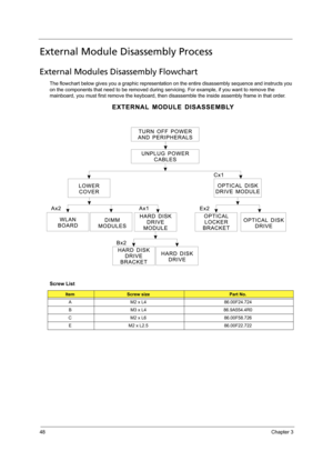
External Modules Disassembly Flowchart
The flowchart below gives you a graphic representation on the entire disassembly sequence and instructs you
on the components that need to be removed during servicing. For example, if you want to remove the
mainboard, you must first remove the keyboard, then disassemble the inside assembly frame in that order.
Screw List
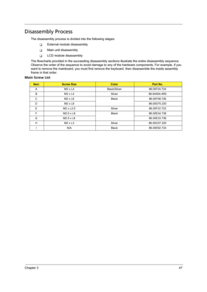
ItemScrew sizePart No.
A M2 x L4 86.00F24.724
B M3 x L4 86.9A554.4R0
C M2 x L6 86.00F58.726
E M2...
Page 59
Chapter 349
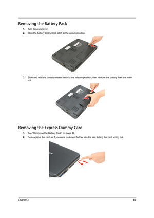
Removing the Battery Pack
1.Turn base unit over.
2.Slide the battery lock/unlock latch to the unlock position.
3.Slide and hold the battery release latch to the release position, then remove the battery from the main
unit.
Removing the Express Dummy Card
1.See “Removing the Battery Pack” on page 49.
2.Push against the card,as if you were pushing it further into the slot, letting the card spring out.
Page 60
50Chapter 3
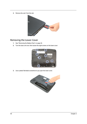
3.Remove the card  from the slot.
Removing the Lower Cover
1.See “Removing the Battery Pack” on page 49.
2.Turn the base unit over, then loosen the eight screws on the lower cover.
3.Use a plastic flat-blade screwdriver to pry open the lower cover.
