Sony Vaio Pcg Serie Pfg Fx777 Manual
Here you can view all the pages of manual Sony Vaio Pcg Serie Pfg Fx777 Manual. The Sony manuals for Notebook are available online for free. You can easily download all the documents as PDF.
Page 1
Confidential
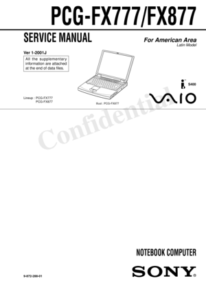
PCG-FX777/FX877
SERVICE MANUAL
NOTEBOOK COMPUTER
9-872-288-01
For American Area
Latin Model
Lineup : PCG-FX777
PCG-FX877
S400
Illust : PCG-FX877
Ver 1-2001J
All the supplementary
information are attached
at the end of data files.
Update List
Page 2
— 2 —
Information in this document is subject to change without notice.
Sony and VAIO are trademarks of Sony. Intel logo and Intel Inside
logo are registered trademarks of Intel Corporation. Pentium MMX
is a trademark of Intel Corporation. Microsoft, MS-DOS, Windows,
the Windows 95 and Windows 98 logo are trademarks of Microsoft
Corporation.
All other trademarks are trademarks or registered trademarks of
their respective owners. Other trademarks and trade names may be
used in this document to refer to...
Page 3
— 3 —
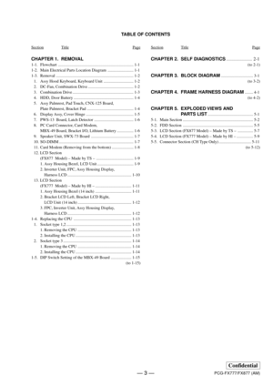
TABLE OF CONTENTS
CHAPTER 1. REMOVAL
1-1. Flowchart ......................................................................... 1-1
1-2. Main Electrical Parts Location Diagram ......................... 1-1
1-3. Removal ........................................................................... 1-2
1. Assy Hood Keyboard, Keyboard Unit ............................. 1-2
2. DC-Fan, Combination Drive ............................................ 1-2
3. Combination Drive...
Page 5
1-1
Confidential
PCG-FX777/FX877 (AM)
CHAPTER 1.
REMOVAL
1-1. Flowchart
• P XX means pages that appears in this manual.
• Remember that hard disk drives are easily damaged by vibration.  Always handle with care.
1-2. Main Electrical Parts Location Diagram
POWER
OFFASSY
HOOD
KEYBOARD
SO-DIMM
BATTERY
PA C K
CARD
MODEM
KEYBOARD
UNIT
P 1-2 P 1-2
P 1-7 P 1-7
P 1-7P 1-5
P 1-8P 1-4P 1-2
P 1-3
P 1-6
P 1-6ASSY
PALMREST
P 1-2
P 1-3P 1-3
DC-FAN
PC CARD
CONNECTOR
FDD
SPEAKER
UNITDOOR
BATTERY
SWX-73
BOARD
P 1-5...
Page 6
1-2
Confidential
PCG-FX777/FX877 (AM)
1-3.Removal
1. Assy Hood Keyboard, Keyboard Unit
2. DC-Fan, Combination Drive
6Assy Hood Keyboard
7
95 q;Keyboard Unit
Four Claws
MBX-49 Board
CN2004 MBX-49 Board
CN1902 3Screw M2X4 Special Head (Black)
8Screw M2X4 Special Head (Black)
1
2 4Pull it up sliding it to the right.
qaCombination Drive 7DC Fan
q; 9Screw M2X6 Special Head (Gold) 2+B M2 (X2) (Gold) 5Screw (M2) 0 Number P3 Kind (X4) (Black)
3Plate ground
MBX-49
Board
CN701
8 4 1
MBX-49 Board
CN1026
Page 7
1-3
Confidential
PCG-FX777/FX877 (AM)
3. Combination Drive
4. HDD, Door Battery
Claw
7Assy Door DVD-RW (PA) 8COMBO Drive5Bracket CD-ROM R
2Bracket (CD-ROM L) 3+B M2 (NOJI) (X2) (Gold)
1+B M2 (NOJI) (X2) (Gold)4+B M2 (NOJI) (X2)
    (Gold)
6Screw (M1.7X3.5) (X3) (Black)
3
2FPC 50Pin
    (for HDD)
4Door Battery 1Screw M2X6 Special Head (X6) (Gold)
1Screw M3X4 (X2) (Gold)
2Screw M3X4 (X2) (Gold)3Bracket HDD
4FPC 50Pin
    (for HDD) 5HDD
MBX-49 Board
CN2201
Page 8
1-4
Confidential
PCG-FX777/FX877 (AM)
5. Assy Palmrest, Pad Touch, CNX-125 Board, Plate Palmrest, Bracket Pad
Assy Palmrest
1Screw M2X4
Special Head
(Black)
4
1M2X4 Special
Head (x4) (Black)
5Bracket Pad
9Pad, Touch
8FPC (TP-CNX)
6FPC (SWX-PWS)
3Plate
Palmrest
7CNX-125
Board
2Screw (M2),
    0 Number P3 Kind (X4) (Black)PWS-13 Board
CN4004
3Pull it to the front slightly
    and raise to remove it.
2
Move down the front
portion slightly
downward and then pull it out.
4Remove by pressing
to rear.
Page 9
1-5
Confidential
PCG-FX777/FX877 (AM)
6. Display Assy, Cover Hinge
Four ClawsqfCover Hinge
qhDisplay Base
qg
Display AssyqaM2X6 Special
    Head (Gold)
8Screw (M2), 0 Number P3 Kind (Black) 9Screw M2X6 Special
Head (Gold)
5Screw M2.6
Cross (Hole)
Bind (Black)7Screw M2.6
Cross (Hole)
Bind (Black)
qs 2
6Screw M2.6 Cross
(Hole) Bind (X2) (Black) q;Screw +B 2X12 (Silver)
Six Claws
MBX-49 Board
CN701
4Plate ground 3+B M2 (X2) (Gold)
qdClose simultaneously both left and right hinges approximately 90°
  in...
Page 10
1-6
Confidential
PCG-FX777/FX877 (AM)
7. PWS-13  Board, Latch Detector
8. PC Card Connector, Card Modem, MBX-49 Board, Bracket I/O, Lithium Battery
∗1 When removing the CPU, refer to “ 1-4. Replacing the CPU ”.
∗2 Modem card can be removed from the bottom.
Refer to the subsequent paragraph “ 11. Card Modem ” for more details.
6PWS-13 Board
3 5Latch Detector
4Two Claws 12Screw M2X4 Special Head (X2) (Black)
MBX-49 Board CON22
qjMBX-49 Board 9PC Card Connector
qdGrip M2 (X2) (Black) 8Screw +B 2X14
(X2)...


