Sony Ae 5 Service Manual
Here you can view all the pages of manual Sony Ae 5 Service Manual. The Sony manuals for Television are available online for free. You can easily download all the documents as PDF.
Page 1
1
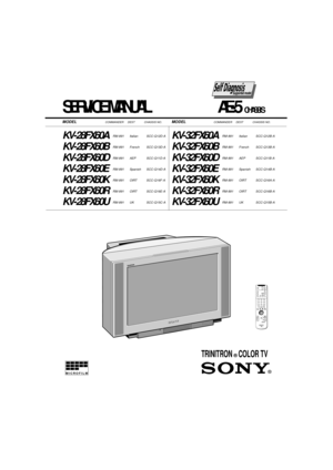
SERVICE MANUAL                          AE-5  CHASSIS
MODEL                              COMMANDER     DEST            CHASSIS NO.MODEL                             COMMANDER     DEST            CHASSIS NO.
KV-28FX60ARM-891 Italian SCC-Q12D-A
KV-28FX60BRM-891 French SCC-Q13D-A
KV-28FX60DRM-891 AEP SCC-Q11D-A
KV-28FX60ERM-891 Spanish SCC-Q14D-A
KV-28FX60KRM-891 OIRT SCC-Q16F-A
KV-28FX60RRM-891 OIRT SCC-Q16E-A
KV-28FX60URM-891 UK SCC-Q15C-A
KV-32FX60ARM-891 Italian SCC-Q12B-A
KV-32FX60BRM-891 French...
Page 2
2
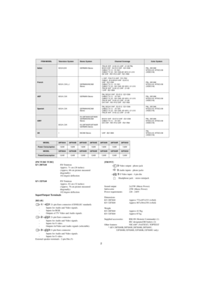
ITEM MODELTelevision SystemStereo SystemChannel CoverageColor System
ItalianB/G/H,D/K GERMAN StereoITALIA VHF : A-H2 (C) UHF : 21-69 PAL
B/G/H VHF : E2-E12 UHF : E21-E69
CABLE TV (1) : S1-S41
CABLE TV (2) : S01-S05,M1-M10,U1-U10
DK VHF : R01-R12 UHF : R21-R69PA L ,  S E C A M
NTSC4.43, NTSC3.58
(VIDEO IN)
French
B/G/H, D/K,L,I GERMAN/NICAM
StereoL VHF : F02-F10 UHF : F21-F60
CABLE : B-Q B/G/H VHF : E2-E12
UHF : E21-E69
CABLE TV (1) : S1-S41
CABLE TV (2) : S01-S05, M1-M10, U1-U10
ITALIA VHF : A-H2 (C)...
Page 3
3
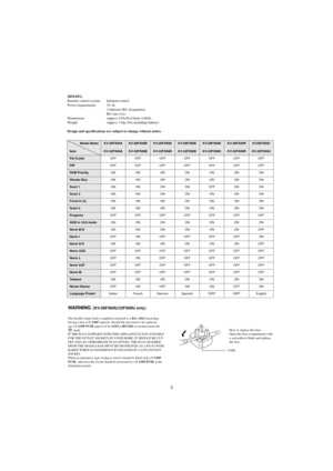
WA R N I N G  (KV-28FX60U/32FX60U only)
The flexible mains lead is supplied connected to a B.S. 1363 fused plug
having a fuse of 5 AMP capacity. Should the fuse need to be replaced,
use  a  5  AMP  FUSE  approved  by ASTA to BS 1362,  i e  o n e  t h a t  c a r r i e s  t h e
       mark.
IF THE PLUG SUPPLIED WITH THIS APPLIANCE IS NOT SUITABLE
FOR THE OUTLET SOCKETS IN YOUR HOME, IT SHOULD BE CUT
OFF AND AN APPROPRIATE PLUG FITTED. THE PLUG SEVERED
FROM THE MAINS LEAD MUST BE DESTROYED...
Page 4
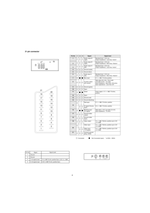
4 21 pin connector
Connected Not Connected (open)    * at 20Hz - 20kHz
L/G/S/I R/D/D/DS333
R/D/D/DL/G/S/I
2S213S31/
19
17
15
13
11
9
7
5
3
1
20
18
16
14
12
10
8
6
4
2 21
Pin No124SignalSignal level
1Audio output B
(right)Standard level : 0.5V rms
Output impedence : Less than 1kohm*
2Audio output B
(right)Standard level : 0.5V rms
Output impedence : More than 10kohm*
3Audio output A
(left)Standard level : 0.5V rms
Output impedence : Less than 1kohm*
4Ground (audio)
5Ground (blue)
6Audio input A...
Page 5
5
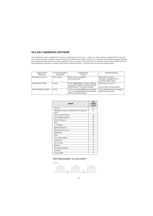
AE-5 SELF DIAGNOSTIC SOFTWARE
The identification of errors within the AE-5 chassis is triggered in one of two ways :- 1: Busy or 2: Device failure to respond to IIC. In the event
of one of these situations arising the software will first try to release the bus if busy (Failure to do so will report with continuous flashing LED) and
then communicate with each device in turn to establish if a device is faulty. If a device is found to be faulty the relevant device number will be dis-
played through the...
Page 6
6
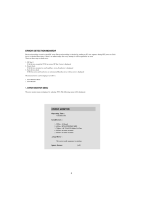
ERROR DETECTION MONITOR
Device acknowledge is used to check IIC errors. Device acknowledge is checked by sending an IIC start sequence during CRT power on. Each
device is checked three times, if there is no acknowledge after every attempt, it will be regarded as an error.
There are three steps to check errors
1. IIC line 0
If all devices except the NVM are errors, IIC line 0 error is displayed
2. Board check
If all devices mounted on one board have errors, board error is displayed
3. Each device...
Page 7
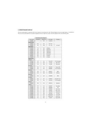
7 2. ERROR READER DISPLAY
The error reader display is connected to the service connector to read actual error codes. The part number for the error reader display is  S-188-900-10.
Once an error has been detected it will then be displayed on the two digit error reader. The errors displayed refer to the following table :
Send Data to Error Reader
Error CodeData highData LowError typeFunction
00 00h - f0h no device
Gen.IIC Error
00 01h f0h 01h IIC 0 line
00 02h f0h 02h IIC 1 line not used
Board Error
01...
Page 8
8
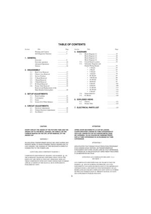
TABLE OF CONTENTS
CAUTION
SHORT CIRCUIT THE ANODE OF THE PICTURE TUBE AND THE
ANODE CAP TO THE METAL CHASSIS, CRT SHIELD, OR THE
CARBON PAINTED ON THE CRT, AFTER REMOVAL OF THE
ANODE CAP
WARNING !!
AN ISOLATING TRANSFORMER SHOULD BE USED DURING ANY
SERVICE WORK TO AVOID POSSIBLE SHOCK HAZARD DUE TO
LIVE CHASSIS. THE CHASSIS OF THIS RECEIVER IS DIRECTLY
CONNECTED TO THE POWER LINE.
SAFETY-RELATED COMPONENT WARNING !!
COMPONENTS IDENTIFIED BY SHADING AND MARKED ON
THE SCHEMATIC DIAGRAMS, EXPLODED VIEWS...
Page 9
9
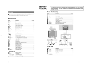
SECTION 1
GENERAL
The operating instructions mentioned here are partial abstracts from the Operating
Instruction Manual. The page numbers of the Operating Instruction Manual remain
as in the manua
l.
28Overview
This section briefly describes the buttons and controls on the TV set and the Remote Control.
Open the flaps at the front and back of his Instruction Manual for detailed illustrations.
For more information refer to the page numbers given in the overview.
Remote ControlSymbol Description See...
Page 10
10
30
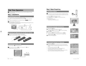
The following chapter contains all the steps necessary when first installing your TV and
the basic TV functions.
Step 1 InstallationA Connecting the TV Set1Connect the TV set to the mains socket (220-240 V. AC, 50 Hz).
2aConnect a conventional aerial cable to the socket marked ù M on the rear of the TV set.
or
2bConnect your Satellite Receiver to one of the Scart connectors  J K L of the TV set.
When connecting a VCR to your TV set:
We recommend that you use the preset function Manual Programme...
