Honeywell Tz 4 Manual
Here you can view all the pages of manual Honeywell Tz 4 Manual. The Honeywell manuals for Control panel are available online for free. You can easily download all the documents as PDF.
Page 1
PRODUCT DATA
68-0259-1
® U.S. Registered Trademark
Copyright © 2002 Honeywell •  All Rights Reserved
TZ-4 TotalZone® Zone Control Panel
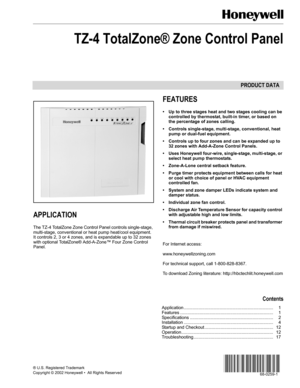
APPLICATION
The TZ-4 TotalZone Zone Control Panel controls single-stage,
multi-stage, conventional or heat pump heat/cool equipment.
It controls 2, 3 or 4 zones, and is expandable up to 32 zones
with optional TotalZone® Add-A-Zone™ Four Zone Control
Panel.
FEATURES
• Up to three stages heat and two stages cooling can be
controlled by thermostat, built-in timer, or...
Page 2
TZ-4 TOTALZONE® ZONE CONTROL PANEL
68-0259-1 2
SPECIFICATIONS
Input Ratings:
Voltage: 20-30 Vac, 50/60 Hz.
Power: 13 VA, nominal.
Output Ratings:
1.5A run, 200,000 cycles (30 Vac). 3.5 inrush.
1.5A run, 100,000 cycles (30 Vac) 7.5A inrush.
Humidity Ratings:
5 to 90 percent RH, non-condensing.
Temperature Ratings:
Shipping: -20° to 120°F.
Operating: -40° to 150°F.
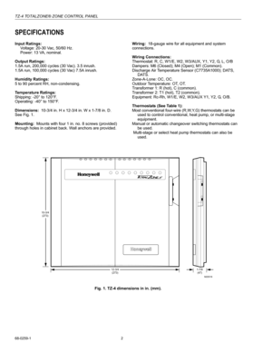
Dimensions:  10-3/4 in. H x 12-3/4 in. W x 1-7/8 in. D.
See Fig. 1.
Mounting:  Mounts with four 1 in. no. 8 screws (provided)
through holes...
Page 3
TZ-4 TOTALZONE® ZONE CONTROL PANEL
3 68-0259-1
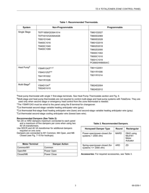
aHeat pump thermostat with single Y first-stage terminals. See Heat Pump Thermostats section and Fig. 6.bMulti-stage and heat pump thermostats are not required to control multi-stage and heat pump systems with TotalZone. They are
used only when second stage or emergency heat control from the zone thermostat is needed.
cThe Y594R1243 must be wired to the panel using the B terminal for changeover.dCut thermostat second-stage variable heating anticipator wire...
Page 4
TZ-4 TOTALZONE® ZONE CONTROL PANEL
68-0259-1 4
INSTALLATION
Mounting
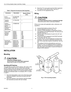
CAUTION
Equipment Damage Hazard.
Do not mount TZ-4 inside HVAC equipment
Mount only on wall or on cold air return.
Identifying DIP Switches
This panel has two banks of DIP switches, DIP switch 4 (S4)
and DIP switch 5 (S5), see Fig 15. Each bank has eight
individual switches that are identified by two numbers; the first
number is the bank number (4 or 5) and the second number
identifies the individual switch. For example, DIP 5-1 is...
Page 5
TZ-4 TOTALZONE® ZONE CONTROL PANEL
5 68-0259-1
Wiring Diagrams (Fig. 3 and 4)
Conventional Thermostats
Conventional (RWYG) thermostats can be used to control
conventional, multi-stage, and heat pump equipment. If the
thermostat has a common terminal, it is wired to C on the
panel, see Fig. 3. A multi-stage thermostat is wired with the
second and third stage of heat to W2 and W3 on the panel
thermostat connections, and with the second stage of cooling
to Y2. Leave the zone O/B thermostat jumper on...
Page 6
TZ-4 TOTALZONE® ZONE CONTROL PANEL
68-0259-1 6
Fig. 4. PC8900 with W8900A,C Thermostat wiring.
Heat Pump Thermostats
Select a heat pump thermostat from Table 1. If the thermostat
selected has a separate Y1 and W1 wire, as shown in Fig. 5,
leave the zone O/B thermostat type jumper on the TZ-4
disconnected, and wire as shown in Fig. 5.If the PC8900/W8900 /Thermostat is used in a heat pump
application, use the W8900A, not the W8900B, and wire as
shown in Fig. 4.
M20508B
W8900A/C IS RECOMMEDED FOR...
Page 7
TZ-4 TOTALZONE® ZONE CONTROL PANEL
7 68-0259-1
.
Fig. 5. Heat pump thermostat with separate Y1 and W1
terminals and multi-stage thermostat wiring.
If the thermostat selected from Table 1 has a single Y terminal
for first stage heat and cool, wire as shown in Fig. 6. Wire
either O or B (not both) from the thermostat to the O/B
terminal on the panel. Locate the O/B thermostat jumper on
the TZ-4 near each zone thermostat wiring terminal. Connect
the jumper if O was used or leave disconnected if B was...
Page 8
TZ-4 TOTALZONE® ZONE CONTROL PANEL
68-0259-1 8
Fig. 7. Heat pump thermostat with 3-stage heat, 2-stage
cool single Y thermostat wiring.
Fig. 8. Wiring ARD or ZD damper to panel.Fig. 9. Wiring AOBD damper to panel.
Fig. 10. Wiring two AOBD dampers in parallel.
MARD Dampers or Dampers Using an ML6161 Motor
Actuator
Wire the MARD Damper or ML6161 Actuator to the panel as
shown in Fig. 11. These are floating control actuators, but are
controlled as two-position devices on the TZ-4 panel. Multiple...
Page 9
TZ-4 TOTALZONE® ZONE CONTROL PANEL
9 68-0259-1
Fig. 12. MARD or ML6161 Damper Motor Actuator using
R8222 Relay wiring.
Transformer
1.Wire the transformers to the panel as shown in Fig. 13.
One 40 VA, 24 Vac transformer controls up to five ARD
or ZD dampers.
2.Connect the transformer to terminals R and C.
3.Add the auxiliary transformer if six to ten ARD or ZD
dampers are used.
a. Wire auxiliary transformer to terminals T1 and T2.
b. It is important that these two transformers be wired
in phase....
Page 10
TZ-4 TOTALZONE® ZONE CONTROL PANEL
68-0259-1 10
Fig. 15. TotalZone Add-A-Zone wiring.
Conventional Equipment
Wire the heating and cooling equipment to the equipment
terminals on the TZ-4 Panel as shown in Fig. 16.
Conventional Equipment: Set DIP switch 5-1 to on.
Electric Furnaces: Set DIP switch 5-6 to off to energize the fan
with a call for heat.
Hydro-Air: Wire the zone valve or circulator relay to the Rh
and W1 equipment terminals. (If the circulator relay has
powered terminals, remove the Rh Rc...


