Asus G73 Service Guide
Here you can view all the pages of manual Asus G73 Service Guide. The Asus manuals for Notebook are available online for free. You can easily download all the documents as PDF.
Page 1
                             Disassembly Procedure

                                                                       V1.0 2 - 1
Disassembly Procedure
Please  follow  the  information  provided  in  this  section  to  perform  the  complete
disassembly  procedure  of  the  notebook. Be  sure  to  use  proper  tools  described
before.
SUS G73 Series Notebook  consists  of  various  modules.  This chapter...
Page 2
                             Disassembly Procedure

                                                                       V1.0 2 - 2
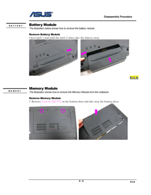
Battery Module
The illustration below shows how to remove the battery module.

Remove Battery Module
Open latch 1 and hold the latch 2 when take the battery away....
Page 3
Disassembly Procedure
V1.0 2 - 3
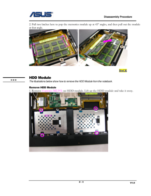
2. Pull two latches here to pop the memories module up at 45 angles, and then pull out the module
at that angle....
Page 4
                             Disassembly Procedure

                                                                       V1.0 2 - 4


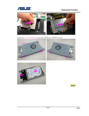
2. Remove 4 screws (M3*4) to separate HDD from HDD housing


                                                                                                                                     BACK


M3*3
M3*3
Page 5
                             Disassembly Procedure

                                                                       V1.0 2 - 5
Wireless LAN Module
The illustration below shows how to remove the Wireless LAN Module from the notebook.

Remove Wireless LAN Module
Disconnect  the  antennas  and  remove 2  screws (M2*4) on  Wireless  LAN  card  and  pull  out  the
card from its slot....
Page 6
                             Disassembly Procedure

                                                                       V1.0 2 - 6
Keyboard Module
The illustrations below show how to remove the Keyboard and disassemble the Keyboard Cover.

Remove the Keyboard
1. Open 5 latches (ESC, F5, F9, PrtSc and End) on keyboard module by a pair of tweezers.


2.  Turn  over  the  keyboard  plate  and  disconnect...
Page 7
                             Disassembly Procedure

                                                                       V1.0 2 - 7
Remove Keyboar d Cable
1. Use a flexible connector tool to unlock the cable connector on both ends (no. 1).
2. Carefully pull out the keyboard cable (no. 2) with a pair of tweezers.
3. Lock the connector (no. 3) again to avoid possible breakage....
Page 8
                             Disassembly Procedure

                                                                       V1.0 2 - 8
Top Case Module
The illustrations below show how to remove and disassemble the Top Case Module of the notebook.

Remove the Top Case Module
1.  Remove 2 screws  (M2*4) on  the  bottom case.  Then  pry  the hinge  cover  by  a  plastic  blade and
remove the hinge cover....
Page 10
                             Disassembly Procedure

                                                                       V1.0 2 - 10
3. Remove 6 screws (M2.5*5) on the top case. Then disconnect the switch board FPC, speaker cable
and the touchpad FPC.


4. Pry the edges of the top case and remove the top case to take it away.


Switch Board
FPC Speaker cable
Touchpad FPC
M2.5*5


