AEM TruBoost Controller Gauge 304350 User Manual
Here you can view all the pages of manual AEM TruBoost Controller Gauge 304350 User Manual. The AEM manuals for Digital Performance Gauges are available online for free. You can easily download all the documents as PDF.
Page 1
ADVANCED ENGINE MANAGEMENT INC.
2205 126th Street Unit A, Hawthorne, CA. 90250
Phone: (310) 484-2322 Fax: (310) 484-0152  http://www.aempower.com
Instruction Part Number: 10-4350 Rev 090506
©  2006 Advanced Engine Management, Inc.

Page 1

Installation Instructions for  AEM Tru Boost
  WARNING:


30-4350
Boost Controller Gauge


This installation is not fo  the electrically or mechanically
challenged! Use th EXTREMEr
is gauge with
,!
 caution! If you are

t
uncomfortable with...
Page 2
Page 2
EM’s  Tru Boost boost controller gauge is a stand-alone boost controller that features a
ree digit LED digital readout with 24 sweep ing multi color LED’s, two programming
uttons, and an on-board pressure sensor.  T he Tru Boost kit contains all necessary
uge assembly
(1) Appearance kit (Silver bezel, silver pin guide, white faceplate)   connector, 6 pieces)
 NPT fitting
itting


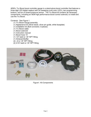
Figure1. Kit Components

A
th
b
components, including an AEM high performance boost control solenoid,...
Page 3
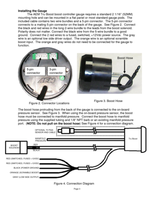
Installing the Gauge The AEM Tru Boost boost controller gauge  requires a standard 2 1/16” (52MM)
ounting hole and can be mounted in a flat  panel or most standard gauge pods.  The
 two  wire bundles and a 5-pin connector.  The 5-pin connector
connec t
 to
m
included cable contains
ts to a mating 5-pin connector on the  back of the gauge.  See Figure 2.  Connec
the black and red wires in the long 2-wire bundle to the leads from the boost solenoid.
Polarity does not matter. Connect the bl ack wire...
Page 4
Scramble Boost Connection (Optional)
Scramble boost is activated when the orange wire is grounded.  Connect t\
he
range wire to ground through a switch
o as shown in Figure 5.


ORANGE(SCRAMBLEBOOST)
Switch
Page 4


Warning Light Connection  (Optional)
The Tru Boost w  is activated.  Connect
e grey wire to a warni


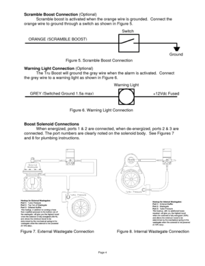
oost Solenoid Connec When energized, ports 1 & 2  are connected, when de-ener gized, ports 2 & 3 are
onnected. The port numbers are clearly noted on the solenoid body.  See...
Page 5
Page 5
xternal Pressure Sensor ble of reading boost levels up to 50 psig when using the
optiona r
.
onfiguring the Tru Boost  ser adjustable options.  Descriptions of each option, along
with th
isplay Units: (UnI - PSI)  e front of the gauge to change the units displayed by the
cramble Boost: (SCb - 10.0)  ty cycle output.  Duty cycle can be set between 10%
cramble Boost Time: (SCr - 0.00)  5.5 seconds) the Tru Boost will output the
ressure Sensor: (SEn - I)  nsor to be used by the Tru Boost....
Page 6
Page 6
larm: (ALA - 30) t pressure at which the al arm will activate.  When the alarm is
lled to
pring Pressure: (SPr – 2.00)  g pressure(3psi less then your spring).  The Tru Boost

ar Graph Full Scale: (FUL – 30)   sweeping LED lights.  The LED light s start at 0 psig
oost Setting A: (AXX – A10)  (10%-90%) for setting A.  For setting A, the duty cycle
le,
oost Setting B: (bXX – b10)  ycle is displayed as “bXX”.
OTE: While configuring the Tru Boos t, the Tru Boost will stay in the
 is turned...
Page 8
Using the Tru Boost
The Tru Boost has 3 running modes.  In all modes, for manifold pressures less
than 0 psig, the sweeping LED’s remain off, the  gauge displays pressure in units of
in-hg, and the displayed values are negative.   In mode A, the gauge will output the duty
cycle selected for boost setting A.  The  gauge will output the duty cycle selected for
boost setting B when in mode B.  In the “OFF ” mode, the solenoid output is turned off.
Press and hold the left button for 2 seconds  to...
Page 9
Error Detection

ErP- If the external sensor is shorted  or disconnected, the LED lights will flash
red and the center digits will display “ErP”.   The error code will not activate when using
the internal pressure sensor.

ErS - If the boost solenoid is shorted or  disconnected, the LED lights will flash red
and the center digits will disp lay “ErS”.  The error code will not activate when the Tru
Boost is on the off mode.  Note: The sole noid always has a small pwm signal to allow
for fault...
Page 10
Page 10

AEM Electronics warranty

Advanced Engine Management Inc. warrants to the consumer that all AEM High
Performance products will be free from defects in material and workmanship for a
period of twelve (12) months  from date of the original purchase. Products that fail within
this 12-month warranty period will be repai red or replaced at AEM’s option, when
determined by AEM that the product failed due  to defects in material or workmanship.
This warranty is limited to t he repair or...


