Home
>
AEM
>
Infinity Plug & Play Engine Harnesses & Universal V8 Core Harnesses
>
AEM GM LS 24x Plug Play Engine Harness 303532 User Manual
AEM GM LS 24x Plug Play Engine Harness 303532 User Manual
Here you can view all the pages of manual AEM GM LS 24x Plug Play Engine Harness 303532 User Manual. The AEM manuals for Infinity Plug & Play Engine Harnesses & Universal V8 Core Harnesses are available online for free. You can easily download all the documents as PDF.
Page 1
AEM Performance Electronics 2205 126th Street Unit A, Hawthorne, CA. 90250 Phone: (310) 484-2322 Fax: (310) 484-0152 http://www.aemelectronics.com Instruction Part Number: 10-3532 2014 AEM Performance Electronics Instruction Manual Infinity Layover Harness GM LS Engines 24x This product is legal in California for racing vehicles only and should never be used on public highways. NOTE: All supplied AEM calibrations, Wizards and other tuning information are...
Page 2
 Rev A, 2013/02/05
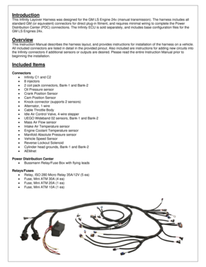
Introduction
This Infinity Layover Harness was designed for the GM LS Engine 24x (manual transmission). The harness includes all
standard GM (or equivalent) connectors for direct plug-in fitment, and requires minimal wiring to complete the Power
Distribution Center (PDC) connections. The Infinity ECU is sold separately, and includes base configuration files for the
GM LS Engines 24x.

Overview
This Instruction Manual describes the harness layout, and provides instructions for...
Page 3
 Rev A, 2013/02/05

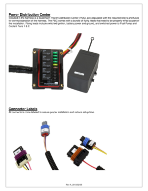
Power Distribution Center
Included in the harness is a Bussmann Power Distribution Center (PDC), pre-populated with the required relays and fuses
for correct operation of the harness. The PDC comes with a bundle of flying leads that need to be properly wired as part of
the installation. Flying leads include switched ignition, battery power and ground, and switched power to Fuel Pump and
Coolant Fans 1 & 2.


Connector Labels
All...
Page 4
 Rev A, 2013/02/05

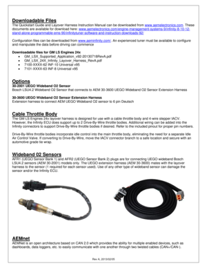
Downloadable Files
The Quickstart Guide and Layover Harness Instruction Manual can be downloaded from www.aemelectronics.com. These
documents are available for download here: www.aemelectronics.com/engine-management-systems-9/infinity-8-10-12-
stand-alone-programmable-ems-90/infinitytuner-software-and-instruction-downloads-92/

Configuration files can be downloaded from www.aeminfinity.com/. An experienced tuner must be available to configure
and manipulate the data before...
Page 5
 Rev A, 2013/02/05

Installation Notes

Wiring Conventions and EMI
The GM LS Engines 24x layover harness comes pre-wired with all connectors, fuses, and relays needed to operate an
engine. However, the PDC does require extension/termination of the flying leads to their appropriate devices, and
additional sensors and other devices can be wired into the harness as needed for the specific application. The following
guidelines should be adhered to while completing the required wiring.

A proper...
Page 6
Rev A, 2013/02/05 Required Wiring The GM LS Engines 24x Layover Harness comes with a flying lead bundle wired into the PDC. Each of the flying leads needs to be wired to an appropriate device, or sealed and tied wrapped if not used. Power and Ground The Infinity must have an electrically secure ground connection, which means that the battery negative must be properly grounded to the battery AND the cylinder head grounds muse be properly grounded to...
Page 7
 Rev A, 2013/02/05

Switched Ignition 12V
The Switched Ignition flying lead (PNK-WHT) must be connected to the output on the ignition switch that supplies 12V
when the switch is in the Start and Run position. The ignition switch output should be isolated, meaning that it is dedicated
to the PNK-WHT wire, and should NOT supply switched ignition power to any other device.


Perm 12V
The Perm 12V/Fused 5A PNK flying lead can be used to power the ignition switch if the switch does not already have...
Page 8
 Rev A, 2013/02/05

GM LS Engines 24x Pinout

C1 Infinity Connector C1 73 Way F Receptacle 0.64 2.8 Series Sealed (GY)
Pin Wire Color Gauge Destination Description 1 2 3 4 5
C1-2 GRN 20 C23-B --- --- --- --- Reverse Lockout Lowside Driver
C1-4 WHT 18 C26-4 --- --- --- --- Deutsch   DTM04-6P   UEGO B1-HEAT
C1-5 GRN 20 C26-2 --- --- --- --- Deutsch   DTM04-6P   UEGO B1-IA
C1-6 RED 20 C26-6 --- --- --- --- Deutsch   DTM04-6P   UEGO B1-IP
C1-7 BLK 20 C26-1 --- --- --- --- Deutsch   DTM04-6P   UEGO...
Page 9
 Rev A, 2013/02/05
C2 Infinity Connector C2 56 Way F Receptacle 0.64 2.8 Series Sealed (BU)
Pin Wire Color Gauge Destination Description 1 2 3 4 5
C2-3 BLK 18 SP-1 --- --- --- --- Battery Ground
C2-4 RED/BLK 20 C11-B --- --- --- --- Injector 7 Control Lowside
C2-5 DK BLU/WHT 20 C12-B --- --- --- --- Injector 8 Control Lowside
C2-8 BRN 20 C4-E --- --- --- --- Coil Signal Ground (Bank 2)
C2-9 PNK/YEL 20 SP-4 --- --- --- --- ECU 12V from EFI-1
C2-13 --- --- --- --- --- --- --- Optional...
Page 10
 Rev A, 2013/02/05
C5 Injector 1 2 Way F Metri-Pack 280.1 Series Pull to Seat (BLK)
Pin Wire Color Gauge Destination Description 1 2 3 4 5
A PNK 20 SP-2 --- --- --- --- Ignition Voltage
B BLK 20 C1-63 --- --- --- --- Fuel Injector 1 Control
         C6 Injector 2 2 Way F Metri-Pack 280.1 Series Pull to Seat (BLK)
Pin Wire Color Gauge Destination Description 1 2 3 4 5
A PNK 20 SP-3 --- --- --- --- Ignition Voltage
B LT GRN/BLK 20 C1-62 --- --- --- --- Fuel Injector 2 Control
         C7 Injector...


