AEM CAS Trigger Disc 308761 User Manual
Here you can view all the pages of manual AEM CAS Trigger Disc 308761 User Manual. The AEM manuals for Sensors Connectors & Accessories are available online for free. You can easily download all the documents as PDF.
Page 1
© 2010 ADVANCED ENGINE MANAGEMENT INC.
2205 126th Street Unit A    Hawthorne, CA. 90250
Phone: (310) 484-2322 Fax: (310) 484-0152
http://www.aempower.com
Instruction Part Number: 10-6620-A supplement

Page 1 of 25
Installation Instructions for:
Crank Angle Sensor replacement for EMS P/N 30-6620
1990-1995 Nissan 300ZX VG30DE, VG30DETT
1989-1998 Nissan Skyline RB26DETT,
1993-1998 Skyline RB25DET,
1989-1994 Skyline RB20DET,
1988-1990 S13 180SX, 200SX and Silvia CA18DET

WARNING:
,!...
Page 2
Page 2 of 25

**Cam / Crank Angle Sensor: AEM trigger disc MUST be used
Discrepancies have been observed in the OEM cam/crank signals between model years
and/or trim levels; to avoid confusion the Series 2 EMS does not support the OEM Nissan
trigger pattern. A replacement trigger disc is now included with every Nissan EMS and
must be installed before attempting to start the engine. The following installation was
performed on a stock 300ZX. Installation in a Skyline or modified 300ZX may require...
Page 3
Page 3 of 25

Instructions:
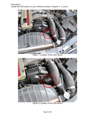
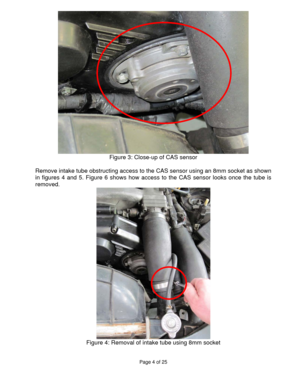
Locate the CAS sensor on your vehicle as shown in figures 1, 2, and 3.


Figure 1: Location of the CAS sensor


Figure 2: Location of the CAS sensor
Page 4
Page 4 of 25


Figure 3: Close-up of CAS sensor

Remove intake tube obstructing access to the CAS sensor using an 8mm socket as shown
in figures 4 and 5. Figure 6 shows how access to the CAS sensor looks once the tube is
removed.

Figure 4: Removal of intake tube using 8mm socket
Page 5
Page 5 of 25


Figure 5: Removal of intake tube using 8mm socket


Figure 6: Intake tube removed to access CAS sensor
Page 6
Page 6 of 25

Mark the three bolts on the CAS sensor with your Sharpie as shown in figures 7 and
8 so that the sensor will go back into its original position upon reinstallation.


Figure 7: Marking position of CAS sensor


Figure 8: Marking position of CAS sensor
Page 7
Page 7 of 25

Remove clip that holds the harness to the CAS sensor using a pick and a pair of
needle-nose pliers as shown in figures 9 and 10. This may be done after removing
the CAS assembly, but is best done now.

Figure 9: Pry here to remove this clip


Figure 10: Remove clip with needle-nose pliers
Page 8
Page 8 of 25


Remove the three bolts on the CAS sensor using a 10mm socket as shown in figure 11.
Take care not to turn the sensor. Mark with your Sharpie so that the sensor can be
reinstalled correctly as shown in figure 12. Figure 13 shows the cam with the CAS
assembly removed. (If you turn the sensor by accident, make sure to align it with cam and
mark it)

Figure 11: Removal of 3 CAS sensor bolts using 10mm socket


Figure 12: Mark shaft relative to housing for correct reinstallation...
Page 9
Page 9 of 25


Figure 13: CAS sensor removed

Remove the three screws holding the CAS assembly together using a ¼” flat
screwdriver (use the flat screwdriver since these screws are tightly installed, but soft)
as shown in figure 14.

Figure 14: Taking apart CAS assembly using number 2 Phillips screwdriver
Page 10
Page 10 of 25


Remove screws holding the seal cover onto the assembly using a ¼” flat screwdriver
as shown in figure 15.

Figure 15: Removing seal cover on CAS assembly using ¼” screwdriver

Screw in the M4x45mm cap screws so that plenty of threads are engaged and lightly
tap the three bolts evenly using a mallet so that the assembly will separate as shown
in figure 16. If prying between the two halves is necessary as shown in figure 17, be
extremely careful not to damage the sensor inside...


