Whirlpool Microwave Mh2175xsb5 Manual
Here you can view all the pages of manual Whirlpool Microwave Mh2175xsb5 Manual. The Whirlpool manuals for Microwave are available online for free. You can easily download all the documents as PDF.
Page 1
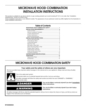
MICROWAVEHOODCOMBINATION
INSTALLATIONINSTRUCTIONS
Thisproductissuitableforuseaboveelectricorgascookingproductsuptoandincluding36(91.4cm)wide.SeeInstallation
Requirementssectionforfurthernotes.
Theseinstallationinstructionscoverdifferentmodels.Theappearanceofyourparticularmodelmaydifferslightlyfromtheillustrationin
theseinstallationinstructions.
TableofContents
MICROWAVEHOODCOMBINATIONSAFETY..............................I...
Page 2
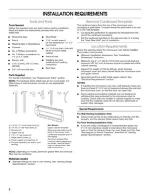
INSTALLATIONREQUIREMENTS
tO0_S3_J
ToolsNeeded
Gathertherequiredtoolsandpartsbeforestartinginstallation.
Readandfollowtheinstructionsprovidedwithanytools
listedhere.
•Measuringtape•Studfinder
•Pencil•7/16socketwrench
(orboxwrench)for1/4x2
•Maskingtapeorthumbtackslagscrews
•Scissors
•11/2(3.8cm)diam.holedrill
•No.2Phillipsscrewdriverbitforwoodormetal
cabinet
•No.3Phillipsscrewdriverfor
1/4-20x3bolts•Keyholesaw
•Electricdrill•Caulkinggunand
weatherproofcaulking...
Page 3
InstallationDimensions
NOTE:Thegrounded3prongoutletmustbeinsidetheupper
cabinet.SeeElectricalRequirementssection.
AB
30(76.2cm)typicam*
12(30.5cm)rain.
14(35.6cm)max. l......
66(167.6cm)rain.
*30(76.2cm)istypicalfor66(167.6cm)installationheight.
Exactdimensionsmayvarydependingontypeofrange/cooktop
below.
T
17¼
(43.8crn] T
16¼
_,1.3cm) ElectricalShockHazard
Plugintoagrounded3prongoutlet.
Donotremovegroundprong.
Donotuseanadapter.
Donotuseanextensioncord....
Page 4
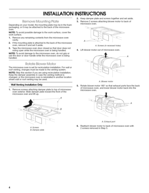
INSTALLATIONINSTRUCTIONS
Dependingonyourmodel,themountingplatemaybeinthefoam
packaging,oritmaybeattachedtothebackofthemicrowave
oven.
NOTE:Toavoidpossibledamagetotheworksurface,coverthe
worksurface.
1.Removeanyremainingcontentsfromthemicrowaveoven
cavity.
2.Ifthemountingplateisattachedtothebackofthemicrowave
oven,removeitandsetitaside.
3.Tapethemicrowaveovendoorclosedsothatdoordoesnot
swingopenwhilethemicrowaveovenisbeinghandled.
NOTE:Toavoiddamagetothemicrowaveoven,donotgripor...
Page 5
7=
Reattachdamperplate.Makesuredamperplatetabsare
insertedintotheslotsinthetopofthemicrowaveoven.
A
%
\
\l B
D
A.Damperplate
B.Screws
C.Damperplatetabs
D.Slots
8.Securedamperplatewith2screwsremovedinStep1.
RoofVentingInstallationOnly
1.RepeatStep1fromWallVentingInstallationOnly.
2.RepeatStep2fromWallVentingInstallationOnly.
3.RepeatStep3fromWallVentingInstallationOnly.
4.RepeatStep4fromWallVentingInstallationOnly.
5.Rotateblowermotorsothatexhaustportsfacethetopof...
Page 6
NOTE:Ifnowallstudsexistwithinthecabinetopening,donot1.Usingastudfinder,locatetheedgesofthewallstud(s)within
installthemicrowaveoven.theopening.
SeeillustrationsinPossibleWallStudConfigurations.2.Markthecenterofeachstud,anddrawaplumblinedown
eachstudcenter.SeeillustrationsinPossibleWallStud
Configurations.
PossibleWallStudConfigurations
Thesedepictionsshowexamplesofpreferredinstallationconfigurationswiththemountingplate.
NoWallStudsatEndHoles
Figure1 NoWallStudsatEndHoles
Figure2
B...
Page 7
Themicrowaveovenmustbeinstalledonaminimumof1wall
stud,preferably2,usingaminimumof1lagscrew,preferably2.
1.Usingmeasuringtape,findandclearlymarkthevertical
centerlineoftheopening.
A......................}Lj__o_
A.Centerline
2.Alignthecentermarkersonthecardboardtemplatetothe
centerlineonthewall,makingsureitislevel,andthatthetop
ofthecardboardtemplateisbuttedupagainstthebottom
edgeoftheuppercabinet.
NOTES:
•Ifthefrontedgeoftheuppercabinetislowerthantheback...
Page 8
5.
InstallationforWallStudatOneEndHole(Figure3)
1.Drilla3/16(5mm)holeintothewallstudattheendhole
markedinStep3ofMarkRearWall.
2.Ifinstallingonasecondwallstud,drilla3/16(5mm)holeinto
thewallstudattheotherholemarkedinStep6ofMarkRear
Wall.RefertoFigure3inPossibleWallStudConfigurations
inLocateWallStud(s)section.
3.Drilla3/4(19mm)holethroughthewallattheotherendhole.
InstallationforWallStudsatBothEndHoles(Figure4)
Drill3/16(5mm)holesintothestudsattheendholesmarkedin
Step3ofMarkRearWall....
Page 9
5.Cutthe11/2(3.8cm)diameterholeatthecircularshadedarea
Gonthetemplate.Thisholeisforthepowersupplycord.
NOTE:Ifuppercabinetismetal,thesupplycordbushingneedsto
beinstalledaroundthesupplycordhole,asshown.
B
A.Metalcabinet
B.Powersupplycordbushing
6.Drill3/8(10mm)holesatpointsDandEonthetemplate.
Thesearefortwo1/4-20x3boltsandwashersusedto
securethemicrowaveoventotheuppercabinet.
ForRoofVentingInstallationOnly
7.Cut3/4(19mm)holeatonecorneroftheshadedrectangular
areaFonUpperCabinetTemplate....
Page 10
NOTE:Ifmicrowaveovendoesnotneedtobeadjusted,skip
steps7-9.
7.Ifadjustmentisrequired,rotatemicrowaveovendownward.
Using2ormorepeople,liftmicrowaveovenoffofmounting
plate,andsetasideonacoveredsurface.
8.Loosenmountingplatescrews.Adjustmountingplateand
retightenscrews.
9.Repeatsteps3-6.
10.Withthemicrowaveovencentered,andwithatleastone
personholdingitinplace,insertboltsthroughuppercabinet
intomicrowaveoven.Tightenboltsuntilthereisnogap
betweenuppercabinetandmicrowaveoven.
NOTES:...


![Page 3
InstallationDimensions
NOTE:Thegrounded3prongoutletmustbeinsidetheupper
cabinet.SeeElectricalRequirementssection.
AB
30(76.2cm)typicam*
12(30.5cm)rain.
14(35.6cm)max. l......
66(167.6cm)rain.
*30(76.2cm)istypicalfor66(167.6cm)installationheight.
Exactdimensionsmayvarydependingontypeofrange/cooktop
below.
T
17¼
(43.8crn] T
16¼
_,1.3cm) ElectricalShockHazard
Plugintoagrounded3prongoutlet.
Donotremovegroundprong.
Donotuseanadapter.
Donotuseanextensioncord.... Page 3
InstallationDimensions
NOTE:Thegrounded3prongoutletmustbeinsidetheupper
cabinet.SeeElectricalRequirementssection.
AB
30(76.2cm)typicam*
12(30.5cm)rain.
14(35.6cm)max. l......
66(167.6cm)rain.
*30(76.2cm)istypicalfor66(167.6cm)installationheight.
Exactdimensionsmayvarydependingontypeofrange/cooktop
below.
T
17¼
(43.8crn] T
16¼
_,1.3cm) ElectricalShockHazard
Plugintoagrounded3prongoutlet.
Donotremovegroundprong.
Donotuseanadapter.
Donotuseanextensioncord....](http://img.usermanuals.tech/thumb/81/99934/w300_microwave-mh2175xsb5-manual-1509409861_d-2.png)


