Sony Cfd 8 Service Manual
Here you can view all the pages of manual Sony Cfd 8 Service Manual. The Sony manuals for Stereo Cassette deck are available online for free. You can easily download all the documents as PDF.
Page 1
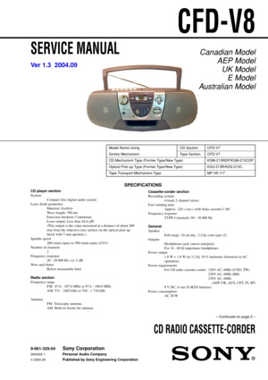
CFD-V8
SERVICE MANUAL
CD RADIO CASSETTE-CORDER
SPECIFICATIONS
Canadian ModelAEP ModelUK Model E Model
A ustralian Model
Model Name Using CD Section CFD-V7
Similar Mechanism Tape Section CFD-V7
CD Mechanism Type (Former Type/New Type) KSM-213RDP/KSM-213CDP
Optical Pick-up Type (Former Type/New Type) KSS-213R/KSS-213C
Tape Transport Mechanism Type MF-V5-117
– Continued on page 2 –
V er 1.3  2004.09
9-961-329-04
2004I02-1
©  2004.09
Sony Corporation
Pe rsonal Audio Company
Published by Sony Engineering...
Page 2
2
CFD-V8
SAFETY-RELATED COMPONENT WARNING!!
COMPONENTS IDENTIFIED BY MARK  0 OR DOTTED LINE WITH
MARK  0 ON THE SCHEMATIC DIAGRAMS AND IN THE PARTS
LIST ARE CRITICAL TO SAFE OPERATION.
REPLACE THESE COMPONENTS WITH SONY PARTS WHOSE
PA RT  NUMBERS APPEAR AS SHOWN IN THIS MANUAL OR IN
SUPPLEMENTS PUBLISHED BY SONY.
T ABLE OF CONTENTS
Specifications ........................................................................\
....... 1
1. SERVICING NOTES...................................................... 3...
Page 3
3
CFD-V8
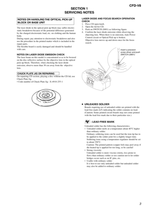
 NOTES ON HANDLING THE OPTICAL PICK-UP
 BLOCK OR BASE UNIT
The laser diode in the optical pick-up block may suffer electro-
static breakdown because of the potential difference generated
by the charged electrostatic load, etc. on clothing and the human
body.
During repair, pay attention to electrostatic breakdown and also
use the procedure in the printed matter which is included in the
repair parts.
The flexible board is easily damaged and should be handled
with care.
NOTES ON LASER DIODE...
Page 4
4
CFD-V8
SECTION 2
GENERAL
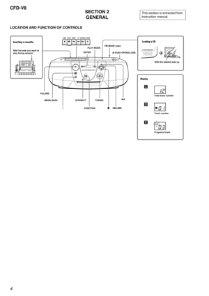
LOCATION AND FUNCTION OF CONTROLS
This section is extracted from
instruction manual.
Loading a CD
With the labeled side up
Inserting a cassette
With the side you want to
play facing upwardZ PUSH OPEN/CLOSE
VOLUME
TUNING PLAY MODE
ENTER
iFUNCTION.,>u
MEGA BASS
x FM MODE (rear)
Display
Total track number
C
Track number
D
Programd track
E
OPR/BATT
Page 5
5
CFD-V8
SECTION 3
DISASSEMBLY
Note :  Follow the disassembly procedure in the numerical order given.
3-1. CABINET (FRONT) SUB ASSY, CABINET (REAR)
3-2. CONTROL BOARD
z The equipment can be removed using the following procedure.
Cabinet (front)  sub ASSY
Control board
Optical pick-up (KSS-213C)
Cabinet (rear)  Cabinet (upper)
Set
Volume board,
FM SW board, Main board
PRE board, Mechanism deck,
Optical pick-up section, CD board
Belt, M601 (capstan/reel motor),
“HRP901 Head, Magnetic (Record/playback)”,...
Page 6
6
CFD-V8
3-3. CABINET (UPPER)
89
6
 two screws +BVTP 3 × 10
5 screw +BVTP 3 × 121 three screws
    +BVTP 3 × 12
4 screw
    +BVTP 3 × 12
remove the handle in the direction of the arrow.
2 open the cassette holder assy by
     pressing STOP/EJECT button.
3 open the Lid (CD)
cabinet (rear)
cabinet (upper)STOP/EJECTbutton
7 CNP902
    (POWER board)
3-4. POWER BOARD, INLET BOARD, BATT (R) BOARD, BATT (L) BOARD
2 two screws
     +BVTP 3 × 10
1 four screws
    +BVTP 3 × 10
INLET board
POWER board
cabinet...
Page 7
7
CFD-V8
3-6. PRE BOARD, MECHANISM DECK, OPTICAL PICK-UP SECTION, CD BOARD
0 three screws
     +BVTP 3 × 10
5screw
     +BVTP 3 × 10
MAIN board
2remove solder
    (five places) FM SW board
6 KH801
S801
7 wire, parallel (CN802)(15 core)
4 remove solder(four places)
VOLUME board cabinet(upper)
1 two screws
     +BVTP 3 × 10
3 qa
9wire, parallel (CNP303)(10 core)
8CNP304
3-5. VOLUME BOARD, FM SW BOARD, MAIN BOARD
optical pick-up section
CD board
mechanism deck
PRE board
1 screw
     +BVTP 3 × 10
5 remove...
Page 8
8
CFD-V8
3-7. BELT, M601 (CAPSTAN / REEL MOTOR), “ HRP901 HEAD, MAGNETIC (RECORD/PLAYBACK) ”,HE901 HEAD (ERASE)
mechanism deck
HE901 head (erase)
HRP901 head, magnetic (record/ playback)
1 two screws
     +B 2.6 × 5
7 claws
5 claws
4 M601
(capstan/reel motor)
2
3 belt
8
6
3-8. OPTICAL PICK-UP (KSS-213C)
4 1
2
5
3 bend the stopper
chassis ASSY, motor (spindle)
shaft, sled
claws
clawclaw
claw
cover, CD
gear
optical pick-up (KSS-213C)
Page 9
9
CFD-V8
SECTION 4
DIAL POINTER INSTALLATION
Note : Follow the installation procedure in the numerical order given.
1 Align the pointer with the groove of “cabinet (front) sub ASSY” and insert it as shown in the illustration.
2 Align knob (TU) with “cabinet (front) sub ASSY” and fasten the screw.
3 Turn the tuning knob fully in the direction of the allow as shown in the illustration.
4 Turn the tuning capacitor gear fully in the direction of the allow as shown in the illustration.
5 Fasten the “cabinet...
Page 10
10
CFD-V8
5-1. MECHANICAL ADJUSTMENTS
PRECAUTION
1. Clean the following parts with a denatured-alcohol-moistened
swab :
record/playback head pinch roller
erase head rubber belts
capstan
2. Demagnetize the record/playback head with a head demagne-
tizer. (Do not bring the head demagnetizer close to the erase
head.)
3. Do not use a magnetized screwdriver for the adjustments.
4. The adjustments should be performed with the rated power sup-
ply voltage (9V) unless otherwise noted.
Torque Measurement
Torque...


