Sony Ba5 Service Manual
Here you can view all the pages of manual Sony Ba5 Service Manual. The Sony manuals for Television are available online for free. You can easily download all the documents as PDF.
Page 1
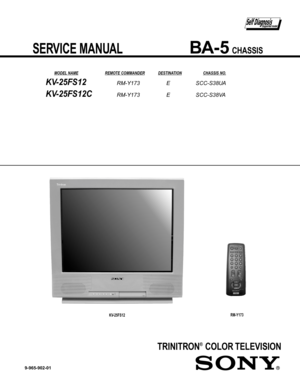
TRINITRON® COLOR TELEVISION
  SERVICE MANUAL            BA-5 CHASSIS
       MODEL NAME REMOTE COMMANDER DESTINATION  CHASSIS NO.
KV-25FS12
9-965-902-01
KV-25FS12 RM-Y173  E  SCC-S38UA
KV-25FS12C RM-Y173  E  SCC-S38VA
RM-Y173
Page 2
— 2 —
KV-25FS12 / 25FS12C
TABLE OF CONTENTS
  Specifi cations...................................................\o.................................................................................... 3
  Warnings and Cautions...................................................\o..................................................................... 4
  Safety Check-out ...................................................\o.............................................................................. 5...
Page 3
— 3 —
KV-25FS12 / 25FS12C
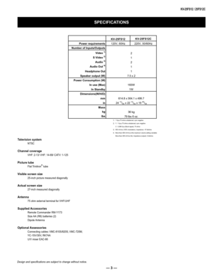
Television system
NTSC
Channel coverage
VHF: 2-13/ VHF: 14-69/ CATV: 1-125
Picture tube
Flat Trinitron® tube
Visible screen size
25-inch picture measured diagonally
Actual screen size
27-inch measured diagonally
Antenna
75 ohm external terminal for VHF/UHF
Supplied Accessories
Remote Commander RM-Y173
Size AA (R6) batteries (2)
Dipole Antenna
Optional Assessories
Connecting cables: VMC-810S/820S, VMC-720M,
YC-15V/30V, RK74A
U/V mixer EAC-66
SPECIFICATIONS
Design and specifi...
Page 4
— 4 —
KV-25FS12 / 25FS12C
WARNINGS AND CAUTIONS
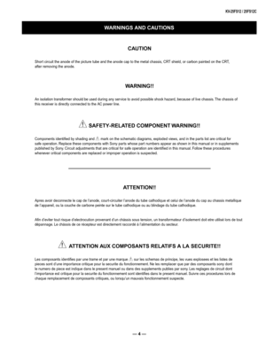
CAUTION
Short circuit the anode of the picture tube and the anode cap to the metal chassis, CRT shield, or carbon painted on the CRT,
after removing the anode.
WARNING!!
An isolation transformer should be used during any service to avoid possible shock hazard, because of live chassis. The chassis of
this receiver is directly connected to the AC power line.
! SAFETY-RELATED COMPONENT WARNING!!
Components identifi ed by shading and ! mark on the schematic...
Page 5
— 5 —
KV-25FS12 / 25FS12C
SAFETY CHECK-OUT
After correcting the original service problem, perform the following
safety checks before releasing the set to the customer:
1.  Check the area of your repair for unsoldered or poorly soldered
connections. Check the entire board surface for solder splashes and
bridges.
2.  Check the interboard wiring to ensure that no wires are “pinched” or
touching high-wattage resistors.
3.  Check that all control knobs, shields, covers, ground straps, and
mounting...
Page 6
— 6 —
KV-25FS12 / 25FS12C
Detected Symptoms
SELF-DIAGNOSTIC FUNCTION
*If a +B overcurrent is detected, stoppage of the vertical defl ection is detected simultaneously.  The symptom that is diagnosed fi rst by the
mircrocontroller is displayed on the screen.
**Refer to Screen (G2) Adjustments in Section 2-4 of this manual.
Display of Standby/Timer LED Flash Count
2 times
4 times
5 times
LED ON 0.3 sec.
LED OFF 0.3 sec.LED OFF
3 sec.
  Diagnostic Item    Flash Count*
  +B Overcurrent    2 times
  V-STOP...
Page 7
— 7 —
KV-25FS12 / 25FS12C
Self-Diagnostic Screen Display
For errors with symptoms such as “power sometimes shuts off ” or “screen sometimes goes out” that cannot be confi rmed, it is possible to bring up
past occurrences of failure on the screen for confi rmation.
To Bring Up Screen Test
In standby mode, press buttons on the Remote Commander sequentially, in rapid succession, as shown below:
Display   Channel 5

    Sound Volume -  Power ON
Self-Diagnostic Screen Display
Numeral “0” means that no fault...
Page 8
— 8 —
KV-25FS12 / 25FS12C
1-1.  REAR COVER REMOVAL
1-2.  CHASSIS ASSEMBLY REMOVAL 1-3.  SERVICE POSITION
SECTION 1:  DISASSEMBLY
2 Screws +BVTP 4x16
Chassis Assembly
CB Board
VB Board
MB BoardA Board 2 Screws +BVTP 4x16
2 Screws +BVTP 4x16
2 Screws +BVTP 3x10
K Board
Page 9
— 9 —
KV-25FS12 / 25FS12C
1.  Discharge the anode of the CRT and remove the anode cap.
2.  Unplug all interconnecting leads from the defl ection yoke, neck
assembly, degaussing coils and CRT grounding strap.
3.  Remove the CB Board from the CRT.
4.  Remove the chassis assembly.
5.  Loosen the neck assembly fi xing screw and remove.
6.  Loosen the defl ection yoke fi xing screw and remove.
7.  Place the set with the CRT face down on a cushion and remove
the degaussing coil holders.
8.  Remove the degaussing...
Page 10
— 10 —
KV-25FS12 / 25FS12C
The following adjustments should be made when a complete
realignment is required or a new picture tube is installed.
These adjustments should be performed with rated power supply
voltage unless otherwise noted.
Set the controls as follows unless otherwise noted:
VIDEO MODE: Standard
PICTURE CONTROL: Normal
BRIGHTNESS CONTROL: Normal
SECTION 2:  SET-UP ADJUSTMENTS
Perform the adjustments in order as follows:
  1.  Beam Landing
  2.  Convergence
  3.  Focus
  4.  Screen (G2)...


