Sharp 14a2s Owners Manual
Here you can view all the pages of manual Sharp 14a2s Owners Manual. The Sharp manuals for Television are available online for free. You can easily download all the documents as PDF.
Page 1
114A1-RU
14A2-RU
1-2 1-1
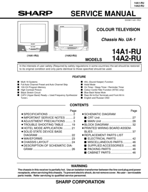
SERVICE MANUAL
(14A1-RU) (14A2-RU)
COLOUR TELEVISION
Chassis No. UA-1
In the interests of user-safety (Required by safety regulations in some countries) the set should be restored
to its original condition and only parts identical to those specified should be used.
14A1-RU
14A2-RU
MODELS
SHARP CORPORATION
WARNING
The chassis in this receiver is partially hot.  Use an isolation transformer between the line cord plug and power
receptacle, when servicing this chassis.  To prevent...
Page 2
2 14A1-RU
14A2-RU
2-2 2-1
IMPORTANT SERVICE NOTES
Maintenance and repair of this receiver should be done by qualified
service personnel only.SERVICE OF HIGH VOLTAGE SYSTEM AND PIC-
TURE TUBEWhen servicing the high voltage system, remove static charge from it by
connecting a 10K ohm Resistor in series with an insulated wire(such as a
test probe) between picture tube  dag and 2nd anode lead.  (AC line cord
should be disconnected from AC outlet.)1. Picture tube in this receiver employs integral  implosion...
Page 3
314A1-RU
14A2-RU
3-2 3-1
ADJUSTMENT PRECAUTIONS
This  models  setting  are  adjusted  in  two  different  ways:  through  the  I
2C  bus  control and  in  the conventional
analog  manner.  The  adjustments via the I
2C bus control include  preset-only items and variable data.
1. Setting the service mode by the microprocessor.
1.  Short JA 122 & JA 124 for 1 second and release to switch to the service mode position, and  the
microprocessor is in input mode. (Adjustment through the I
2C bus control). (Use...
Page 4
4 14A1-RU
14A2-RU
4-2 4-1
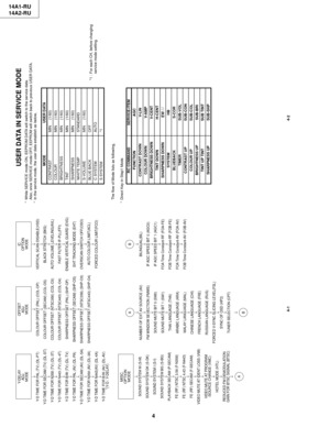
Y-DELAY
ADJ.
MODE
¯
Y-D TIME FOR PAL (TV) (DL-PT)
¯
Y-D TIME FOR SECAM (TV) (DL-ST)
¯
Y-D TIME FOR N358 (TV) (DL-3T)
¯
Y-D TIME FOR N443 (TV) (DL-4T)
¯
Y-D TIME FOR B/W (TV) (DL-TV)
¯
Y-D TIME FOR PAL (AV) (DL-PA)
¯
Y-D TIME FOR SECAM (AV) (DL-SA)
¯
Y-D TIME FOR N358 (AV) (DL-3A)
¯
Y-D TIME FOR N443(AV) (DL-4A)
¯
Y-D TIME FOR B/W (AV) (DL-AV)
*(Y-D : Y-DELAY)OFFSET
ADJ.
MODE
¯
COLOUR OFFSET (PAL) (COL-OP)
¯
COLOUR OFFSET (SECAM) (COL-OS)
  ¯
COLOUR OFFSET (NTSC358) (COL-O3)
¯...
Page 5
514A1-RU
14A2-RU
5-2 5-1
EEPROM ITEMS OSD DATA LENGTH
INITIAL DATA
FIX/ADJ REMARK
VERTICAL SCAN DISABLE VSD
0(DISABLE)/1(ENABLE)
0 FIX
BLACK STRETCH BKS
0(DISABLE)/1(ENABLE)
1 FIX
AUTOMATIC VOLUME LEVELING AVL
0(DISABLE)/1(ENABLE)
1 FIX
FAST FILTER IF-PLL FFI
0(DISABLE)/1(ENABLE)
0 FIX
ENABLE VERTICAL GUARD (RGB BLANKING)
EVG
0(DISABLE)/1(ENABLE)
1 FIX ONLY BLK
EHT TRACKING MODE (HCO) EHT
0(DISABLE)/1(ENABLE)
1 FIX
OVERSCAN SWITCH OFF OSO
0(DISABLE)/1(ENABLE)
0 FIX
AUTO COLOUR LIMIT ACL...
Page 6
6 14A1-RU
14A2-RU
6-2 6-1
INITIAL SETTING
(1).  In service mode, After execute select POS 1, store the following tuning data in EEPROM.
MCL1
CH-NO Fv (MHz) SOUND SYS
MCL1
CH-NO Fv (MHz) SOUND SYS01 48.25 B/G2 62.25 B/G3 77.25 D/K4 175.25 B/G5 182.25 B/G6 183.25 D/K7 191.25 D/K8 196.25 B/G9 199.25 M10 210.25 B/G11 224.25 B/G12 471.25 B/G13 487.25 I14 503.25 B/G15 575.25 B/G16 583.25 B/G17 599.25 B/G18 621.25 M19 639.25 D/K20 703.25 B/G21 735.25 I22 767.25 B/G23 815.25 B/G24 855.25 I25 855.25 B/G26 55.25...
Page 7
714A1-RU
14A2-RU
7-2 7-1
PURITY ADJUSTMENT
No. Adjusting point Adjusting procedure/conditions Waveform and others
PURITY ADJ.1. Receive the GREEN-ONLY signal. Adjust the
beam current to about 500 mA.
2. Degauss the CRT enough with the degausing coil.
Note: Follow the Job Instruction Sheet to ad-
just the magnetic field.
Vertical Bv : +0.040 mT (0.40 gauss)
Horizontal Bh: +0.020 mT (0.20 gauss)
(See page 6.)
3. Maintain the purity magnet at the zero magnetic
field and keep the static convergence roughly...
Page 8
8 14A1-RU
14A2-RU
8-2 8-1
CRT CUT-OFF, BACKGROUND AND SUB-CONTRAST ADJUSTMENTNo. Adjusting point Adjusting procedure/conditions Waveform and others
CRT CUTOFF
ADJUSTMENT
(I
2C BUS
CONTROL)1. Switch TV to VIDEO mode,BLUE BACK OFF, with
NO VIDEO signal.
2. Press R/C to set Picture Normal condition.
3. Connect the oscilloscope to Red OUT from
IC801.(TP851)
Range : 1 V/Div    (DC)
Sweep : 5 msec/Div
4. Adjust SCREEN VR ,so that the tip of signal reach
3.0 Vdc + 0.1 Vdc. 1
1 V 3.0Vdc
0
Maximum
beam check1....
Page 9
914A1-RU
14A2-RU
9-2 9-1
No. Adjusting point Adjusting procedure/conditions Waveform and others
SUB-TINT (I
2C
BUS CON-
TROL)1. Receive the NTSC3.58 Colour Bar signal
through AV in.
2. Connect the oscilloscope to TP853 (Pin (5) of
P882) BLUE-OUT.
ÈRange : 100mV/div. (AC)(Use Probe 10:1)
ÈSweep time : 10 msec/div.
3. Call the SUB-TINT mode in service mode. Ad-
just the SUB-TINT bus data to obtain the wave-
form shown as Fig. 9.
4. Clear the SERVICE mode. 1
NTSC CHROMA ADJUSTMENT
No. Adjusting point...
Page 10
10 14A1-RU
14A2-RU
10-2 10-1
FUNCTION OPERATION CHECKING (VIDEO AND AUDIO)
(Continued)
No. Adjusting point Adjusting procedure/conditions Waveform and others
COLOUR
SYSTEM1. Receive the PAL COLOUR BAR signal, press
the COLOUR SYSTEM key to select modes ex-
cept PAL, check the COLOUR is not working prop-
erly. Then, select the PAL mode. Check again
its colour so that it is working properly.
2. Receive NTSC 4.43/3.58 COLOUR BAR signal
thru AV, press COLOUR SYSTEM key to select
modes except N4.43/3.58,...


