LG 20lc1r Service Manual
Here you can view all the pages of manual LG 20lc1r Service Manual. The LG manuals for Television are available online for free. You can easily download all the documents as PDF.
Page 1
LCD TV
SERVICE MANUAL
CAUTION
BEFORE SERVICING THE CHASSIS,
READ THE SAFETY PRECAUTIONS IN THIS MANUAL.
CHASSIS : CL-81
MODEL : 20LC1R-ZG
website:http://biz.LGservice.com
e-mail:http://www.LGEservice.com/techsup.html
Page 2
- 2 -
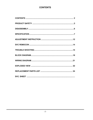
CONTENTS
CONTENTS .............................................................................................. 2
PRODUCT SAFETY ..................................................................................3
DISASSEMBLY ..........................................................................................6
SPECIFICATION ........................................................................................7
ADJUSTMENT INSTRUCTION...
Page 3
- 3 -
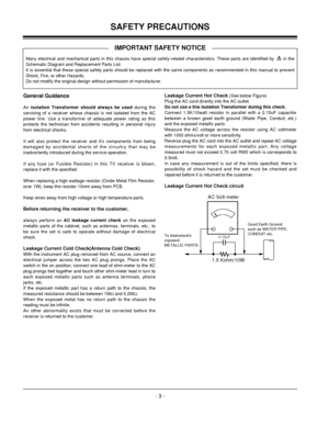
SAFETY PRECAUTIONS
Many electrical and mechanical parts in this chassis have special safety-related characteristics. These parts are identified by      in the
Schematic Diagram and Replacement Parts List.
It is essential that these special safety parts should be replaced with the same components as recommended in this manual to prevent
Shock, Fire, or other Hazards.
Do not modify the original design without permission of manufacturer.
General Guidance
An isolation Transformer should always be...
Page 4
- 4 -
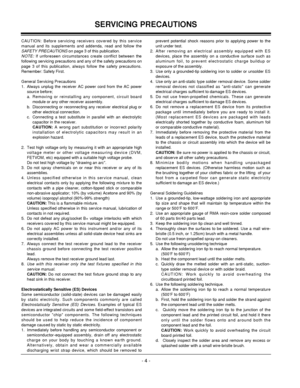
CAUTION: Before servicing receivers covered by this service
manual and its supplements and addenda, read and follow the
SAFETY PRECAUTIONSon page 3 of this publication.
NOTE: If unforeseen circumstances create conflict between the
following servicing precautions and any of the safety precautions on
page 3 of this publication, always follow the safety precautions.
Remember: Safety First.
General Servicing Precautions
1.  Always unplug the receiver AC power cord from the AC power
source before;
a....
Page 5
- 5 -
IC Remove/Replacement
Some chassis circuit boards have slotted holes (oblong) through
which the IC leads are inserted and then bent flat against the
circuit foil. When holes are the slotted type, the following technique
should be used to remove and replace the IC. When working with
boards using the familiar round hole, use the standard technique
as outlined in paragraphs 5 and 6 above.
Removal
1.  Desolder and straighten each IC lead in one operation by gently
prying up on the lead with the...
Page 6
- 6 -
DISASSEMBLY
#1#2 Detached stand assy (Remove the screws)
#3 Disassembly stand assy#4 Detached Backcover (Remove the screw)
#5 Open the Backcovers latch with jig#6 Unlock latch between Cabinet and Backcover
Page 7
- 7 -
SPECIFICATION
1. Application range
This specification is applied to CL-81 chassis.
2. Requirement for Test
Testing for standard of each part must be followed in below
condition.
(1) Temperature: 25°C ± 2°C
(2) Humidity: 65% ± 10%
(3) Power: Standard input voltage (AC 100-240V, 50/60Hz)
(4) Measurement must be performed after heat-run more than
30min.
(5) Adjusting standard for this chassis is followed a special
standard.
3.General Specification
4. Mechanical Specification
No.
Item
Specification...
Page 8
- 8 -
6.Optical Character
ItemRemark Specification
Viewing Angle

Luminance
Contrast Ratio
CIE Color CoordinatesAll White/All Black
In AV Input
PSM : Dynamic
White
(100 IRE) R/L,
U/D
Luminance(cd/
)
Variation
CRTyp
88/88
88/88
450
350
0.313
0.329
0.283
0.298
0.274
0.286 Min
85/85
85/85
380
280
0.283
0.299
0.253
0.268
0.244
0.256 WHITE
(Warm)
WHITE
(Normal)
WHITE
(Cool)Wx
Wy
Wx
Wy
Wx
WyMax
1.3
0.343
0.359
0.313
0.328
0.304
0.316 No.
1
2
3
4
5. Reference table-Function
No.
ItemSpecification
Remark
1...
Page 9
- 9 -
7. Outgoing Condition
No Item Condition Remark
1 Power Off
2 Volume Level 30
3 Main Picture Input TV
4 Main Last Channel Pr 01
5 Mute Off
6 Station Auto Program
Manual Program
Program Edit
Favorite Program None
7 Picture PSM Dynamic
CSM Normal
Dynamic Contrast 100
Brightness 50
Colour 70
Sharpness 50
Tint 0 NTSC OPTION
8 Sound SSM Flat
AVL Off
Balance 0
9 Special Input TV
Child Lock Off
Power Indicator On
Language English(Area Management)
10 Time Clock -- : --
Off Time -- : -- Off
On Time -- : --...
Page 10
- 10 -
8-1.General Specification
8.Engineering Specification
1
2
3Power Supply
Normal
Stand By
Cut-off Switch off
ITEM
D-SUB Pin   Configuraion
Control FunctionH/V Sync
On/On
Off/Off
-
Spectification
1: RED
3: Blue
5: S.T(GND)
7: Green GND
9: N.C
11: ID0(GND)
13: H-Sync
15: SCL
1) Contrast/Brightness/Colour/Sharpness/(Tint)
2) Power On/Off, Input select, Menu, OK
Volume(
,), PR(,)2: Green
4: ID2(GND)
6: RED GND
8: Blue GND
10: D-GND
12: SDA
14: V-Sync
Shell: GNDRemark
For SVC Only Video
Active
Off
-Power...


