Honeywell Rth111b1001u Manual
Here you can view all the pages of manual Honeywell Rth111b1001u Manual. The Honeywell manuals for Thermostat are available online for free. You can easily download all the documents as PDF.
Page 1
R T H 111 / R T H 2 2 1                          1/869-2060EFS-02
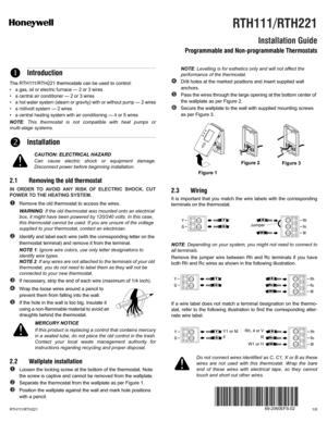
The RTH111/RTH221 thermostats can be used to control:
• a gas, oil or electric furnace — 2 or 3 wires
• a central air conditioner — 2 or 3 wires
• a hot water system (steam or gravity) with or without pump — 2 wires
• a millivolt system — 2 wires
• a central heating system with air conditioning — 4 or 5 wires
NOTE: This thermostat is not compatible with heat pumps or
multi-stage systems.
CAUTION: ELECTRICAL HAZARD
Can cause electric shock...
Page 2
R T H 111 / R T H 2 2 1                          2/8
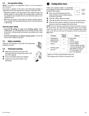
2.4 Fan operation setting
NOTE: This setting is not applicable if there is no fan connected to
the G terminal.
The jumper is located on the back of the thermostat faceplate. It
determines how the fan operates when placed in Automatic mode.
•HG (factory setting): Leave the jumper in this position for gas or oil
heating systems. In this position, the heating system controls the
fan operation and activates the fan only when the plenum air is
sufficiently...
Page 3
R T H 111 / R T H 2 2 1                                              3/8
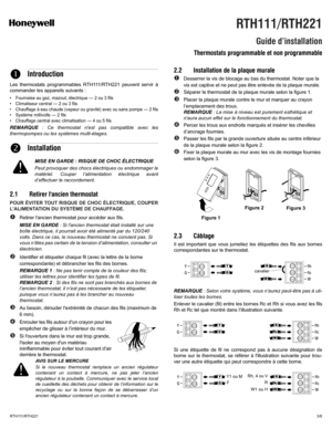
Les thermostats programmables RTH111/RTH221 peuvent servir à
commander les appareils suivants :
• Fournaise au gaz, mazout, électrique — 2 ou 3 fils
• Climatiseur central — 2 ou 3 fils
• Chauffage à eau chaude (vapeur ou gravité) avec ou sans pompe — 2 fils
• Système millivolts — 2 fils
• Chauffage central avec climatisation — 4 ou 5 fils
REMARQUE : Ce thermostat nest pas compatible avec les
thermopompes ou les systèmes...
Page 4
R T H 111 / R T H 2 2 1                                              4/8
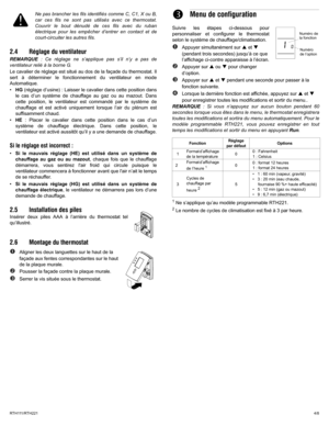
Ne pas brancher les fils identifiés comme C, C1, X ou B,
car ces fils ne sont pas utilisés avec ce thermostat.
Couvrir le bout dénudé de ces fils avec du ruban
électrique pour les empêcher d’entrer en contact et de
court-circuiter les autres fils.
2.4 Réglage du ventilateur
REMARQUE : Ce réglage ne s’applique pas s’il n’y a pas de
ventilateur relié à la borne G.
Le cavalier de réglage est situé au dos de la façade du thermostat. Il...
Page 5
R T H 111 / R T H 2 2 1                                              5/8
Los termostatos programables RTH111/RTH221 pueden usarse para
controlar los siguientes aparatos:
• Calefactor a gas, aceite o eléctrico de 2 ó 3 cables
• Aire acondicionado central de 2 ó 3 cables
• Sistema de agua caliente (vapor o gravedad) con o sin bomba de
2 cables
• Sistema de milivoltios de 2 cables
• Calefacción central con aire acondicionado - 4 ó 5 cables
NOTA: este termostato no es compatible con bombas de calor ni con...
Page 6
R T H 111 / R T H 2 2 1                                              6/8
Retirar el cable de puente entre los terminales Rh y Rc, si estuvieran
presentes los dos cables Rh y Rc, como se indica en la siguiente
ilustración:
Referirse a la siguiente ilustración en el caso de que un cable no
correspondiera con la identificación de un terminal en el termostato,
para encontrar el cable alternativo correspondiente:
No conectar los cables identificados con las letras C, C1,
X o B, puesto que dichos cables no se...


