Brother Db2-b757-3 Manual
Here you can view all the pages of manual Brother Db2-b757-3 Manual. The Brother manuals for Sewing Machine are available online for free. You can easily download all the documents as PDF.
Page 1
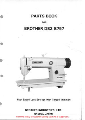
PARTS BOOK
FOR
BROTHER 082-8757
;
...... ____ _
/
•BROTHER•

e .... , l(il fJ rfjlll
High Speed Lock  Stitcher  (with Thread  Trimmer)
BROTHER INDUSTRIES, LTD.
NAGOYA, JAPAN
From  the library  of: Superior  Sewing Machine  & Supply  LLC
Page 3
Notes for using this parts  book
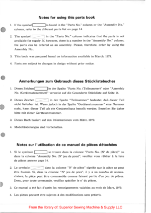
1. If the symbol! L ___ ...~I is found in the Parts No. column or the Assembly No.
column, refer to the different parts list on page 14.
2. The symbol 1=-----------::1 in the Parts No. column indicates that the parts is not
available for supply. If, however, there is a number in the Assembly No. column,
the parts can be ordered as an assembly. Please, therefore, order by using the
Assembly No ..
3 .
This book was prepared based on information available in March,...
Page 4
Notas para usar este Libro  de Piezas
1. De haber un slmbolo I  I junto al Parts No. (Numero de Pieza) o en Ia
columna del Assembly No. (Numero de Juego), habra que mirar Ia Iista de piezas
separada de Ia pagina 14.
2. El slmbolo /~/. que se encuentra en Ia columna del Numero de Pieza,
quiere decir que nose dispone de dicha pieza sola. Cuando, empero, hay un numero
en Ia columna del Numero de Juego, se podra ordenar Ia pieza con todo el juego.
Por lo tanto, sera mejor hacer el pedido recurriendo...
Page 7
c
C. Lower Shaft and Feed  Mechanism
2
3-3-1/
3-t~% 23-2---4
Ref. Nmnc of Parts No. C-I  Ft,.•d Bar Sha ft C -2 Feed Bed c. 3 R in g
C -4 Screw ~· 0 Feed  Do g . · ~6 O il  Cap .  7 Feed Sha ft  Bush in g Small c . 8 Screw C -9 Thrust l~ing C -10 Feed Bar  Arm C-11 Scre w ---C-12 Screw C-1 3
Ft:cd Ro ck  Shaft
C -14 Screw C-1 5 Feed Rock Shaft Arm C :l6 Feed Shaft  Bu sh in g L ef t C-17 Screw C-18 Lower Shaft
C -19 F elt C -2 0 S cre w
C.: ! I Bobbin Cas e llolde r Position Bracket C -22 Screw...
Page 8
D. Feed Mechanism
Ref. Name of Parts Qty No.
0- 1-1 Vertical Feed Eccentric Wheel I
0 -
1·2
Screw 2
0 - 2
Ve rtic a l Feed Connecting Rod I l>· 3  Stopper I
0 - 4-1
Eccentric Whee l I
0 ·  4-2 Screw 2
() . 5-1 Screw 2
0-5· 2 Crank Rod I
0 -
6 Screw I
() .  7-1 Feed Con troller Shaft I [) .  7-2 Screw I 0-7-3 Nut I 0-7-4 Feed Controller I 0-8 Stop Ring I 0· 9  Connecting Plate I D-10 Screw 2 D
·ll Spring I D -12 Spring I D-1 3 Pin I D -14·1 Length Control Screw I 0 -14·2 Packing I
0 -14·3...
Page 9
E. Presser Foot and Knee Lifter Mechanism --- 19-1-e tl--20 16-1 17-4 r- /. 18 ··~ / . ~ ------17-l~-- ,------ l __ _ 19-2 11 ,. ~ ~~ 13 25 12 23-• 23-J Ref. N arne of Parts Qty Parts No. Assembly No. Ref. Name of Parts No. No. E· I Scre w I 141207 ·0·01 E-17· 1 Nut E· 2 Nut I 14 7846· 0-0 I E-17·2 Presse r Bar Lift in g Cam E· 3 Presser Spring Bar I 141 2 0 8 ·0·0 1 E-17·3 Presser Bar Lif tin g Shaft E · 4 Sprin g I 14 172 8·0·0 I E-17·4 Presser Bar Li ft in g Lev er...
Page 10
F. Lubrication
Ref. Name of Parts Qty Parts No. Assembly No. No. F· I Wick I 108804·0·01 F· 2 Wick I 109405-0-01 F· 3 Tube Stopper I 148806-0-01 F· 4 Screw I 009670-5-12
F · 5 Felt Support I 145737-0-01 F· 6  Dust Cover with Tube I 145792·0 ·01 F· 7 Screw I 151603-0 -02 F· 8 Upper Oil Tube I 146329·0·00
F · 9 Tube Guard I 146326-0-01
F -10 Oil Hole Bolt for Oil Gauge I 143196-0-01
F -11 Packing I 081014-6-70
F-12  Oil Gauge Window I 104547-0-01
F-13  Oil Gauge Flange I 104546-0-01
F-14 Screw 4  I...


