Bose 251 environmental speakers Sold from February 2000 User Manual
Here you can view all the pages of manual Bose 251 environmental speakers Sold from February 2000 User Manual. The Bose manuals for Speaker System are available online for free. You can easily download all the documents as PDF.
Page 1
OwOOwner
ltkjeThe Bose® 251TM Environmental Speakers
Owner’s Guide
October 30, 2001
AM250811_04_V.pdf
Page 2
2 October 30, 2001         AM250811_04_V.pdf
For your records…
Serial numbers are located on the label on the back of each 251TM environmental speaker.
Serial numbers: and
Dealer name:
Dealer phone: Purchase date:
We suggest you keep your sales slip and warranty card together with this owner’s guide.
in accordance with EMC Directive 89/336/EEC and Article 10(1) of the
Directive, is in compliance with the following norm(s) or document(s):
Technical regulations: EN50081-1, EN50082-1
Accredited by:
Bose...
Page 3
AM250811_04_V.pdf                                                         October 30, 2001                                                                          3
Where to find…
Setting Up
Before you begin ........................................................................................................... 4
Unpacking the carton ................................................................................................... 4
Tools required...
Page 4
4 October 30, 2001         AM250811_04_V.pdf
Setting Up
Before you begin…
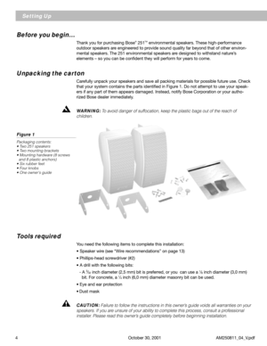
Thank you for purchasing Bose® 251TM environmental speakers. These high-performance
outdoor speakers are engineered to provide sound quality far beyond that of other environ-
mental speakers. The 251 environmental speakers are designed to withstand nature’s
elements – so you can be confident they will perform for years to come.
Unpacking the carton
Carefully unpack your speakers and save all packing materials for possible future...
Page 5
AM250811_04_V.pdf                                                         October 30, 2001                                                                          5
Selecting the location for your speakers
For best results, mount both speakers on the same wall, facing the listening area. Make sure
they do not face each other. (Outdoors, if you are not using an existing wall, consider the
length of your listening area as your “wall.”)
The 251
TM speakers should be placed at least 7 feet (2 m) apart....
Page 6
6 October 30, 2001         AM250811_04_V.pdf
Installing Your 251TM Speakers
Installing the mounting brackets
The 251TM speakers should be mounted using the supplied brackets. They can be mounted
onto the exterior of a house or onto a deck railing or table. If you choose not to use the
supplied brackets, be sure to position your 251 speakers on a sturdy surface.
CAUTION: If you do not use the supplied brackets, choose a level surface for the speak-
ers. Vibration can cause the speakers to move, so it is...
Page 7
AM250811_04_V.pdf                                                         October 30, 2001                                                                          7
Installing Your 251TM  Speakers
Figures 6A and 6B
Installing the hardware
A. Wood
B. Concrete
A.B.
3⁄32 inch (2.25 mm)
3⁄32 inch (2.25 mm)1
1⁄2 inch (2.25 mm)
1
1⁄2 inch (2.25 mm)
1⁄4 inch (6.35 mm)
1⁄4 inch (6.35 mm)1
1⁄2 inch (2.25 mm)
1
1⁄2 inch (2.25 mm)
Figure 7
251 environmental speaker
mounted onto a deck railing or
t
Installing...
Page 8
8 October 30, 2001         AM250811_04_V.pdf
Installing Your 251™ Speakers
Figure 12
Sliding the speakers into the
brackets
Figure 10
Installing the bracket onto a
deck railing or table
Figure 11
Installing the knobs
Attaching the speakers to the brackets
Once the brackets are installed, carefully follow these steps to attach the speakers to the
brackets. First, insert the knobs into each side of the speakers. Be sure to turn each knob
two full rotations (Figure 11). Then, carefully slide the speakers...
Page 9
AM250811_04_V.pdf                                                         October 30, 2001                                                                          9
Installing Your 251TM Speakers
Figures 13A and 13B
Temporarily tighten the
speakers to the brackets
A. Exterior of the house
B. Deck railing or table
Making the connections
Preparing the speaker wire (not provided)
Speaker cord consists of two insulated wires. The insulation around one wire is striped,
collared, or ribbed. This marked wire...
Page 10
10 October 30, 2001         AM250811_04_V.pdf
Installing Your 251TM Speakers
Connecting the speaker wire to the receiver or amplifier
1.  Connect the speakers on the left side of the listening area to the left channel of your
   receiver or amplifier (Figure 17).
   a. Attach the marked wire to the red (+) terminal.
   b. Attach the plain wire to the black (–) terminal.
2.  Connect the speaker on the right side of the listening area to the right channel of your
   receiver or amplifier, following the...


