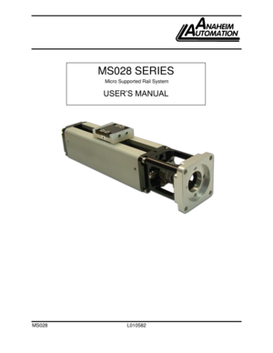
Anaheim Linear Actuator MS028 Table Manual
Here you can view all the pages of manual Anaheim Linear Actuator MS028 Table Manual. The Anaheim manuals for Linear Actuator are available online for free. You can easily download all the documents as PDF.
Page 2
MS028 L010582 2


Anaheim Automation’s MS028 Series Users Guide


This manual, as well as the software described in it, is furnished under license and may be used
or copied only in accordance with the terms of such license. The content of this manual is
furnished for informational use only, is subject to change without notice and should not be
construed as a commitment by Anaheim Automation.  Anaheim Automation assumes no
responsibility or liability for any errors or inaccuracies...
Page 3
MS028 L010582 3

Contents

Using This Manual ..................................................................................................................... 4
Product Returns ......................................................................................................................... 4
Unpacking and Handling ............................................................................................................ 4
Assembly Diagram...
Page 4
MS028 L010582 4
Using This Manual

The MS028 Series are small packaged positioning stage systems which in a standard
configuration include a step motor and coupling.  The MS028 has a cross sectional size of
28mm x 28mm, travel lengths up to 205mm, an anti-backlash TFE coated leadscrew and a
square rail supported carriage for mounting a load.
This manual provides the basic information necessary to unpack, set up, and configure the
MS028.  If additional information is required beyond...
Page 5
MS028 L010582 5
Assembly Diagram


Specifications & Dimensions
Part Number

Maximum
Dynamic
Load (lbs)

Travel
(MM)

Lead
(in)

Accuracy
(in/in)
Max Linear Speed
(in/sec)
Lead-screw
Efficiency
Coeff of
Friction
(Constant)
Drag
Torque
(in/oz)
Motor
Torque
(oz in)
MS028-010-XX-X 5 10 .100 .0006 2.5 69 .09 < .5 8.3
MS028-025-XX-X 5 25 .100 .0006 2.5 69 .09 < .5 8.3
MS028-040-XX-X 5 40 .100 .0006 2.5 69 .09 < .5 8.3
MS028-055-XX-X 5 55 .100...
Page 6
MS028 L010582 6


Travel
in (mm)
Dim A
in (mm)
Dim B
in (mm) Qty C Qty D 0.39 (10) 2.05 (52) .325 (8.3) 4 1 0.98 (25) 2.64 (67) .687 (17.2) 4 1 1.57 40) 3.23 (82) .325 (8.3) 6 2 2.17 (55) 3.82 (97) .687 (17.4) 6 2 2.76 (70) 4.41 (112) .325 (8.3) 8 3 3.35 (85) 5.00 (127) .325 (8.3) 10 4 3.94 (100) 5.59 (142) .687 (17.4) 10 4 4.53 (115) 6.18 (157) .325 (8.3) 12 5 5.12 (130) 6.77 (172) .687 (17.4) 12 5 5.71 (145) 7.36 (187) .325 (8.3) 14 6 6.30 (160) 7.96 (202) .687 (17.4) 14 6 6.89...
Page 7
MS028 L010582 7
Part Number Configuration

The part number for the Microstage MS028 is determined as follows:

Mounting the MS028

Threaded mounting holes are located on the underside of the housing.  The holes for the
MS028 are 4-40 UNC with a .125” depth.  Generally it is best to have through holes matching
the pattern of the mounting holes in the surface to which it is to be secured such that 4-40
screws pass through the surface and into the threads in the housing of this manual...
Page 8
MS028 L010582 8
Step Motor Information

The standard motor which comes with the MS028 is a 1.8° hybrid step motor with four leads.
This motor can be connected to all bipolar step motor driver/controller.  Full torque will be
available from the motor when used with a drive which has a rated output with at least .67 amps
per phase.  Here are the ratings for the standard MS028 step motor:
Electrical Rating Information

Other motors are available from Anaheim Automation including longer...
Page 9
MS028 L010582 9

Limit Switch Information

If your MS028 has the optional limit switches they will be mounted on the side of the stage
housing and are adjustable.  Depending on the driver used the limit switches can be configured
as end-of-travel limits and/or one of them can be configured as a home switch.
The limits are SUNX model PM-L24, an infrared U-channel switch which is interrupted by a flag
mounted to the moving carriage of the MS028.  The output of the switches is NPN open-...
Page 10
MS028 L010582 10


Generally, Output 2 will be used because the switch output will then go ON when the flag
interrupts the switch.  In addition, for safety the switch will appear triggered (shutting down
travel) if there is a break in the wiring to the switch.
If further more detailed information is required for the sensor, please refer to this URL:
http://www.sunx-ramco.com/SunxPDFFiles/PM.pdf .


