AEM Series 2 Plug Play EMS 306611 User Manual
Here you can view all the pages of manual AEM Series 2 Plug Play EMS 306611 User Manual. The AEM manuals for Series 2 Plug & Play EMS are available online for free. You can easily download all the documents as PDF.
Page 1
© 2010 Advanced Engine Management, Inc.
ADVANCED ENGINE MANAGEMENT INC.
2205 126
th Street Unit A    Hawthorne, CA. 90250
Phone: (310) 484-2322 Fax: (310) 484-0152
http://www.aempower.com
Instruction Part Number: 10-6611

Page 1 of 13

Installation Instructions for:
EMS P/N 30-6611

Vehicle:
1996-1998 Nissan 240SX S14 KA24DE
1997-1999 Nissan Sentra B14 SR20DE & GA16DE (Except 97 2.0L)
1997-1998 Nissan 200SX B14 SR20DE & GA16DE (Except 97 2.0L)
1996-1999 Nissan Altima U13 KA24DE...
Page 2
Page 2 of 13
Thank you for purchasing an AEM Engine Management System.

The AEM Engine Management System (EMS) is the result of extensive development on a
wide variety of cars. Each system is engineered for your particular application. The AEM
EMS differs from all others in several ways. The EMS is a stand alone system, which
completely replaces the factory ECU and features unique Plug and Play Technology. This
means that each system is configured especially for your make and model of car without...
Page 3
Page 3 of 13
Read and understand these instructions BEFORE attempting to install this product.

**Cam / Crank Angle Sensor: AEM trigger disc MUST be used

Discrepancies have been observed in the OEM cam/crank angle signals between model
years and/or trim levels; to avoid confusion the Series 2 EMS does not support the OEM
Nissan trigger pattern. A replacement trigger disc is now included with every Nissan EMS
and must be installed before attempting to start the engine. An AEM trigger disc is...
Page 4
Page 4 of 13
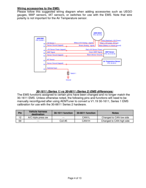
Wiring accessories to the EMS:
Please follow this suggested wiring diagram when adding accessories such as UEGO
gauges, MAP sensors, IAT sensors, or switches for use with the EMS. Note that wire
polarity is not important for the Air Temperature sensor.

3550 63 AEM EMS
P/N: 30-6611
66
50 49 46
50Switched Input
Ground
Switch 1
Sensor Ground (tapped)Air Temperature Sensor
P/N: 30-2010 IAT Sensor
O2 Sensor 1
+5V Sensor Power (tapped)
Sensor Ground (tapped) MAP SignalSensor Ground...
Page 5
Page 5 of 13
1)  Install AEMTuner software onto your PC
The latest version of the AEMTuner software can be downloaded from the AEMTuner
section of the AEM Performance Electronics forums. Series 2 units are not supported
by the older AEMPro tuning software.

2)  Remove the Stock Engine Control Unit
a) Disconnect the negative terminal from battery
b) Access the stock Engine Control Unit (ECU). The location of the ECU on the Nissan
240SX vehicles is behind the kick-panel on the passenger side of...
Page 6
Page 6 of 13  b)
Start the engine and make whatever adjustments may be needed to sustain a safe
and reasonably smooth idle. Verify the ignition timing: Select Wizards>>Ignition
Timing Sync from the pull-down menu.  Click the ‘Lock Ignition Timing’ checkbox
and set the timing to a safe and convenient value (for instance, 10 degrees BTDC).
Use a timing light and compare the physical timing numbers to the timing value you
selected. Use the Sync Adjustment Increase/Decrease buttons to make the...
Page 7
Page 7 of 13  b)
If the EMS is not firing the coils or injectors at all, open the Start tab and look for the
‘Stat Sync’d’ channel to turn ON when cranking. This indicates that the EMS has
detected the expected cam and crank signals;  if Stat Sync’d does not turn on,
monitor the Crank Tooth Period and T2PER channels which indicate the time
between pulses on the Crank and T2 (Cam) signals. Both of these channels should
respond when the engine is cranking, if either signal is not being detected or...
Page 8
Page 8 of 13
Application Notes for EMS P/N 30-6611
KA24DE, GA16DE, SR20DE

Make:
Nissan/Infiniti   Description
Function  ECU Pin #
Model:
240SX, Sentra, 200SX, Altima, G20    Spare Injector Drivers:
Injector 5  29
Years Covered:
1996-1999    Spare Injector Drivers:
Injector 6  30
Engine Displacement:
1.6L, 2.0L, 2.4L    Spare Injector Drivers:
Injector 7  31
Engine Configuration:
Inline 4    Spare Injector Drivers:
Injector 8  32
Firing Order:
1-3-4-2    Spare Injector Drivers:...
Page 9
Page 9 of 13
 Connection Diagram for EMS P/N 30-6611
PnP Means the Plug and Play system comes with this configured for proper operation of this
device. Is still available for reassignment by the end user.
Available  Means the function is not currently allocated and is available for use
Dedicated  Means the location is fixed and cannot be changed
Not used  Means that the AEM EMS does not use this pin location for this application

Pin
1996-1998 Nissan 240SX S14 KA24DE (OBDII) 1997-1999 Nissan...
Page 10
Page 10 of 13

Connection Diagram for EMS P/N 30-6611
Pin
1996-1998 Nissan 240SX S14 KA24DE (OBDII) 1997-1999 Nissan Sentra B14 SR20DE & GA16DE (Except 97 2.0L) 1997-1998 Nissan 200SX B14 SR20DE & GA16DE (Except 97 2.0L) 1996-1999 Nissan Altima U13 KA24DE (Except 96 Non CA models) 1999 Infiniti G20 P10 SR20DE
AEM EMS 30-6611 I/O Notes
20 Start Signal  Start  Input Dedicated, start signal
21 Air Conditioner Switch  Switch 6  Input PnP for air conditioning switch
22 M/T Neutral Position Switch...


