AEM Series 2 Plug Play EMS 306040 User Manual
Here you can view all the pages of manual AEM Series 2 Plug Play EMS 306040 User Manual. The AEM manuals for Series 2 Plug & Play EMS are available online for free. You can easily download all the documents as PDF.
Page 1
ADVANCED ENGINE MANAGEMENT INC. 2205 126 th Street Unit A Hawthorne, CA. 90250 Phone: (310) 484-2322 Fax: (310) 484-0152 Http://www.aempower.com Instruction Part Number: 10-6040, rev A (Oct 2009) 2009 Advanced Engine Management, Inc. Page 1 of 11 Installation Instructions for: EMS P/N 30-6040 1992-1995 Civic / Del Sol / Integra 90-95 Accord / Prelude (2.1L Only) WARNING: ! This installation is not for the tuning novice nor the PC illiterate! Use this system with...
Page 2
Page 2 of 11
Thank you for purchasing an AEM Engine Management System.

The AEM Engine Management System (EMS) is the resul t of extensive development on a
wide variety of cars. Each system is engineered for  the particular application. The AEM
EMS differs from all others in several ways. The EM S is a stand alone system, which
completely replaces the factory ECU and features un ique Plug and Play Technology,
which means that each system is configured especial ly for your make and model of car...
Page 3
Page 3 of 11
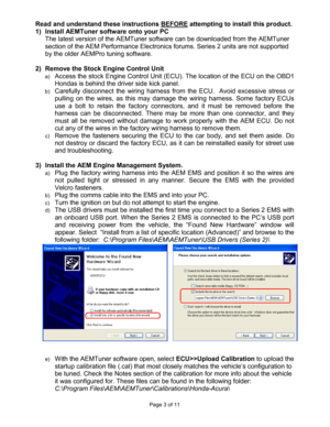
Read and understand these instructions BEFORE attempting to install this product.
1)  Install AEMTuner software onto your PC   The latest version of the AEMTuner software can be  downloaded from the AEMTuner
section of the AEM Performance Electronics forums.  Series 2 units are not supported
by the older AEMPro tuning software.

2)  Remove the Stock Engine Control Unit
a) Access the stock Engine Control Unit (ECU). The loc ation of the ECU on the OBD1
Hondas is behind the driver...
Page 4
Page 4 of 11
f)
Set the throttle range: Select Wizards>>Set Throttl
e Range and follow the on-
screen instructions. When finished, check that the  ‘Throttle’ channel never indicates
less than 0.2% or greater than 99.8%, this is consi dered a sensor error and may
cause some functions including idle feedback and ac celeration fuel to operate
incorrectly.
4)  Ready to begin tuning the vehicle.
a) Before  starting  the  engine,  verify  that  the  fuel  pu mp  runs  for  a  couple  of  seconds...
Page 5
Page 5 of 11
Application Notes for EMS P/N 30-6040

Make:  Honda    Spare Injector Drivers:  Inj 5, Pin A8
Model:  Integra/Civic/Prelude/Accord   Spare Injector Drivers:  Inj 6, Pin A6
Years Covered:  1990-1995    Spare Injector Drivers:  I nj 7, Pin A16
Engine Displacement:  1.5L - 2.2L    Spare Injector Drivers:  Inj 8, Pin A14
Engine Configuration:  Inline 4    Spare Injector Driv ers:  Inj 9, Pin D4
Firing Order:  1-3-4-2    Spare Injector Drivers:  Inj  10, Pin A11
N/A, S/C or T/C:  N/A...
Page 6
Page 6 of 11

Solution for distributed ignition ‘kick back’ when cranking:
With  the  Series  1  EMS,  some  vehicles  would  experien ce  erratic  ignition  timing  at  low
RPM.  The most  noticeable  symptom  would be  an  engine   that  ‘kicks  back’  when  cranking,
and  in  some  cases  the  EMS  would  count  timing  errors   or  lose  ‘Stat  Sync’  at  low  engine
speeds.
These  problems  have  been  eliminated  by  adjusting  ca libration  settings  in  Series  2  Honda
EMS startup...
Page 7
Page 7 of 11
Connection Diagram for EMS P/N 30-6040
Pin # OBD1 Honda / Acura AEM EMS 30-6040 I/O Availability
A1 Injector 1  Injector 1  Output PnP for Injector 1
A2 Injector 4  Injector 4  Output PnP for Injector 4
A3 Injector 2  Injector 2  Output PnP for Injector 2
A4 VTEC Solenoid Valve  High Side Driver 1  Output PnP for VTEC Solenoid
A5  Injector 3  Injector 3  Output PnP for Injector 3
A6 Primary 02 Heater Control  Injector 6  Output Avail, Injector Gnd, 1.5A max
A7  Fuel Pump Relay  Low...
Page 8
Page 8 of 11

Pin # OBD1 Honda / Acura AEM EMS 30-6040 I/O Availability
B1
Power Source 2  +12V Switched  Both Dedicated
B2  Logic Ground 2  Power Ground  Both Dedicated
B3  ---  Coil 3  Output Avail, Rising Edge Trigger Coil Out
B4 ---  Coil 4  Output Avail, Rising Edge Trigger Coil Out
B5 A/C Switch Signal  Switch 3  Input PnP for A/C Switch Signal
B6  ---  Coil 2  Output Avail, Rising Edge Trigger Coil Out
B7 ---  ADCR13  Input Avail, 0-5 Volt Input, 100k pull up
B8 Power Steering Pressure...
Page 9
Page 9 of 11

Pin # OBD1 Honda / Acura AEM EMS 30-6040 I/O Availability
D1
Voltage Back Up  Permanent +12V  Input Dedicated
D2 Brake Switch (Except Prelude)  EGT 2  Input Avail, jumper set for 0-5V Input
D3  Knock 1  Knock 1  Input Dedicated
D4 Service Check Connector  Injector 9  Input Avail, Injector Gnd, 1.5A max
D5  ---  EGT 1  Input Avail, jumper set for 0-5V Input
D6 VTEC Pressure Switch  Switch 4  Input Avail, Switched Input
D7  Data Link Connector  High Side Driver 1 Output Avail, same...
Page 10
Page 10 of 11
30-1040 (Series 1) vs 30-6040 (Series 2)  OBD1 Honda EMS pin differences:
The EMS functions assigned to certain pins have bee n changed and no longer match the
30-1040 EMS. Unless otherwise noted, the following  pins and functions will need to be
manually reconfigured after using AEMTuner to conve rt a V1.19 (30-1100, Series 1 EMS)
calibration for use with the 30-6100 Series 2 hardw are.


Pin OBD1 Honda / Acura  30-1040 function 30-6040 function Notes
A22  Ignition Control Module...


