Home
>
AEM
>
Infinity Plug & Play Harnesses
>
AEM Nissan 19891998 Skyline GTR RB26DETT 303515 User Manual
AEM Nissan 19891998 Skyline GTR RB26DETT 303515 User Manual
Here you can view all the pages of manual AEM Nissan 19891998 Skyline GTR RB26DETT 303515 User Manual. The AEM manuals for Infinity Plug & Play Harnesses are available online for free. You can easily download all the documents as PDF.
Page 1
P/N  3 0-3 515
1 989-1 998 N is san  S kylin e G T-R
  R B26D ETT
A EM  In fin it y  P nP  H arn ess
AEM  P erfo rm ance E le ctr o nic s
A EM  P erfo rm ance E le ctr o nic s, 2 205 1 26th  S tr e et U nit  A , H aw th orn e, C A 9 0250
P hone: ( 3 10) 4 84-2 322  F a x: ( 3 10) 4 84-0 152
h ttp ://w ww.a em ele ctr o nic s.c om
I n str u ctio n P art N um ber: 1 0-3 515
D ocum ent B uild  1 0/2 9/2 015
I
n str u ctio n
M an ual
W ARNIN G : T his  in sta lla tio n is  n ot fo r th e tu nin g n ovic e !...
Page 2
P/N  3 0-3 515
2
© 2 015 A EM  P erfo rm ance E le ctr o nic s
OVE R VIE W
T he 3 0-3 515 A EM  In fin it y  P nP  H arn ess A dapte r w as d esig ned to  ru n 1 989-1 998 N is san S kylin e G T-R  w it h
R B26D ETT e ngin es. T his  is  a  tru e s ta ndalo ne s yste m  th at e lim in ate s th e u se o f  th e N is san E CU a nd m ass a ir flo w
s ensors . T he In fin it y  E CU s upports  th e fa cto ry  C AS (C am  A ngle  S ensor), s o re pla cin g th e d is k w it h in  th e C AS is
n ot
 re quir e...
Page 3
DO W NLO ADABLE F IL ES
3
© 2 015 A EM  P erfo rm ance E le ctr o nic s
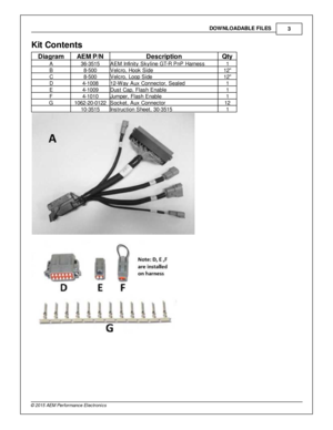
Kit  C onte n ts
Dia g ra m
AEM  P /N
Descrip tio n
Qty
A 36-3 515
AEM  In fin it y  S kylin e G T-R  P nP  H arn ess
1
B 8-5 00
Velc ro , H ook S id e
12
C 8-5 00
Velc ro , L oop S id e
12
D 4-1 008
12-W ay A ux C onnecto r, S eale d
1
E 4-1 009
Dust C ap, F la sh E nable
1
F 4-1 010
Ju m per, F la sh E nable
1
G 1062-2 0-0 122
Socket, A ux C onnecto r
12
10-3 515
In stru ctio n S heet, 3 0-3 515
1
Page 4
P/N  3 0-3 515
4
© 2 015 A EM  P erfo rm ance E le ctr o nic s
Im porta n t A pplic atio n N ote s
T he 3 0-3 515 A EM  In fin it y  P nP  H arn ess a llo w s fo r a   p lu g a nd p la y in sta lla tio n o f  e it h er a n A EM  In fin it y -6  o r
I n fin it y -8 h* E CU to  a  1 989-1 998 N is san S kylin e e quip ped w it h  o ne o f  th e fo llo w in g e ngin es:
1 989-1 998 RB26D ETT  2.6 L  D O HC I-6 , T w in  T urb o
1 989-1 994 RB20D ET  2.0 L  D O HC I-6 , S in gle  T urb o
1 993-1 998 RB25D ET...
Page 5
Im porta nt A pplic a tio n N ote s
5
© 2 015 A EM  P erfo rm ance E le ctr o nic s
IN FIN IT Y A DAPTE R  H A RNESS
T he A EM  In fin it y  P lu g a nd P la y H arn ess c onnects  b etw een th e O EM  N is san h arn ess a nd th e A EM  In fin it y  E CU,
c om ple te ly  re pla cin g th e O EM  E CU. T he h arn ess c onnectio ns fo r th e v a rio us s ensors  a nd a uxilia ry  o ptio ns a re
d escrib ed h ere .
Page 6
P/N  3 0-3 515
6
© 2 015 A EM  P erfo rm ance E le ctr o nic s
C onnectio ns
L am bda - T his  6 -w ay D TM -s ty le  c onnecto r
p lu gs d ir e ctly  in to  a n o ptio nal  A EM  U EG O
e xte nsio n h arn ess, A EM  P /N  3 0-3 600. T he
B osch L S U 4 .2  U EG O S ensor, A EM  P /N  3 0-
2 001, w ill  p lu g in to  th at e xte nsio n h arn ess.
R efe r to  U EG O S ensor  s ectio n fo r m ountin g
r e quir e m ents .
A UX - T his  1 2-w ay c onnecto r is  u sed to
a dapt m any c om mon a ncilla ry  in...
Page 7
In sta lla tio n
7
© 2 015 A EM  P erfo rm ance E le ctr o nic s
In sta lla tio n
1 ) R em ove  th e p assenger s id e k ic k p anel  to
g ain  a ccess to  th e E CU. U nbolt  th e E CU
b ra ckets  to  re m ove  th e E CU.
2 ) R em ove  th e p la stic  w ir e  c ove r a nd lo osen
t h e b olt  in  th e c ente r o f  th e m ain  E CU
c onnecto r. A s th e b olt  is  lo osened, g ently
r o ck th e c onnecto r s id ed to  s id e to  re m ove  it
f r o m  th e E CU.
Page 8
P/N  3 0-3 515
8
© 2 015 A EM  P erfo rm ance E le ctr o nic s
3 ) In sert th e O EM  w ir e  h arn ess c onnecto r
i n to  th e A EM  In fin it y  P nP  a dapte r h arn ess.
G ently  tig hte n th e b olt  a nd d ra w  th e
c onnecto r in to  th e a dapte r h arn ess. M ake
s ure  th e c onnecto r d oes n ot s kew  to  o ne
s id e. V erify  th e c onnecto r is  fu lly  s eate d a nd
s nug th e b olt . D o n ot fo rc e th e c onnecto r, d o
n ot o ve r tig hte n th e b olt .
4 ) P lu g in  th e a ddit io...
Page 9
In sta lla tio n
9
© 2 015 A EM  P erfo rm ance E le ctr o nic s
5 ) P lu g in  th e 8 0-p in  c onnecto r to  th e In fin it y
E CU. S win g th e la tc h o ve r to  d ra w  th e
c onnecto r d ow n in to  p osit io n. T he la tc h w ill
c lic k in  p osit io n. S lid e th e th e re d lo ck in to
p la ce to  s ecure  th e la tc h. U se th e s upplie d
V elc ro  s trip s to  s ecure  th e E CU in to  p la ce
b ehin d th e k ic k p anel.
Page 10
P/N  3 0-3 515
1 0
© 2 015 A EM  P erfo rm ance E le ctr o nic s
PIN O UTS
In fin ity -6  P /N  3 0-7 106, In fin ity -8 h P /N  3 0-7 108*
In fin it y
P in
Hard ware
R efe re n ce
Nis san
F unctio n
Nis san
P in  D estin atio n
Hard ware  S pecif ic atio n
Note s
C1-1
Low sid eS wit c h_4
A/C
C om pre ssor
C2-9
Low sid e s w it c h, 1 .7 A  m ax, N O
i n te rn al  f ly back d io de. 1 2v  p ullu p.
Config ure d in  B ase S essio n f o r A /C  C om pre ssor C lu tc h
c ontro l.  M ay  b e re assig ned in...


