AEM CAS Trigger Disc 308760 User Manual
Here you can view all the pages of manual AEM CAS Trigger Disc 308760 User Manual. The AEM manuals for Sensors Connectors & Accessories are available online for free. You can easily download all the documents as PDF.
Page 1
2010 ADVANCED ENGINE MANAGEMENT INC. 2205 126th Street Unit A Hawthorne, CA. 90250 Phone: (310) 484-2322 Fax: (310) 484-0152 http://www.aempower.com Instruction Part Number: 10-6600-A supplement Page 1 of 9 Installation Instructions for: Crank Angle Sensor replacement for EMS P/N 30-6600 89-94 Nissan 240SX S13 KA24DE 91-94 Nissan Sentra B13 GA16DE 90-94 Nissan Pulsar GTi-R N14 SR20DET 91-93 Nissan NX B13 GA16DE 93-94 Nissan Altima U13 KA24DE 89-95 Nissan Bluebird U13 SR20DET 91-93...
Page 2
Page 2 of 9

**Cam / Crank Angle Sensor: AEM trigger disc MUST be used
Discrepancies  have  been  observed  in  the  OEM  cam/crank  angle  trigger  discs  between
model years and/or trim  levels;  to avoid  confusion the  Series  2  EMS  does not  support  the
OEM Nissan trigger pattern. A replacement trigger disc is now included with every Nissan
EMS and must be installed before attempting to start the engine. The following installation
was performed on a stock Nissan S13 240SX so your...
Page 3
Page 3 of 9

Instructions with photos on the following pages:

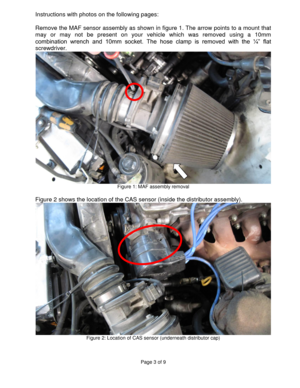
Remove the MAF sensor assembly as shown in figure 1. The arrow points to a mount that
may  or  may  not  be  present  on  your  vehicle  which  was  removed  using  a  10mm
combination  wrench  and  10mm  socket.  The  hose  clamp  is  removed  with  the  ¼”  flat
screwdriver.
 Figure 1: MAF assembly removal

Figure 2 shows the location of the CAS sensor (inside the distributor assembly).
 Figure 2: Location of CAS sensor...
Page 4
Page 4 of 9


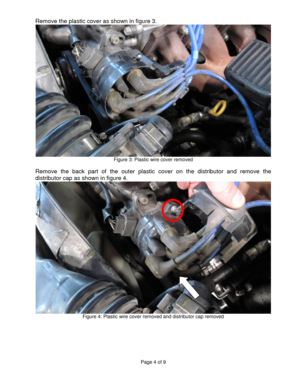
Remove the plastic cover as shown in figure 3.
 Figure 3: Plastic wire cover removed

Remove  the  back  part  of  the  outer  plastic  cover  on  the  distributor  and  remove  the
distributor cap as shown in figure 4.
 Figure 4: Plastic wire cover removed and distributor cap removed
Page 5
Page 5 of 9

Remove  the  distributor  rotor  with  carefully  with  the  pry  bar  as  shown  in  figure  5,  taking
note  of  how  the  rotor  was  oriented  on  the  shaft.  (The  photo  shows  a  different  distributor
that has the same type of rotor installation)

 Figure 5: Distributor rotor removed with pry bar

Remove the internal plastic cover shown in figure 6.
 Figure 6: Internal plastic cover to be removed
Page 6
Page 6 of 9

Remove the internal CAS disc cover shown in figure 7 with a #2 Phillips screwdriver.
 Figure 7: Removal of internal CAS disc cover

Remove the screw holding the CAS disc and collar as shown in figure 8 with the #2
Phillips screwdriver (Make sure screwdriver is firmly planted since this screw will be very
tight).
 Figure 8: Original CAS disc removal
Page 7
Page 7 of 9

Figure 9 shows the original CAS disc with the collar that holds it in place removed. The
original disc can be removed now. For future use, the original disc should be marked UP
to remember what the original orientation of the disc is.
 Figure 9: Original CAS disc with collar removed

The new AEM trigger disc is installed as shown in figure 10, orientation up or down is not
important, only the D-shaped mounting on the shaft.
 Figure 10: AEM CAS trigger disc installed
Page 8
Page 8 of 9


The collar and screw can be reinstalled as shown in figure 11.
 Figure 11: Trigger disc and collar reinstalled

The internal CAS disc cover can be reinstalled with two screws that held it in place as
shown in figure 12.
 Figure 12: Trigger disc cover reinstalled
Page 9
Page 9 of 9


The internal plastic cover is reinstalled as shown in figure 13.
 Figure 13: Internal plastic cover reinstalled

Reassemble the rest of the items in the reverse order of disassembly.
Page 10
2010 ADVANCED ENGINE MANAGEMENT INC. 2205 126th Street Unit A Hawthorne, CA. 90250 Phone: (310) 484-2322 Fax: (310) 484-0152 http://www.aempower.com Instruction Part Number: 10-6600-B supplement Page 1 of 9 Installation Instructions for: Crank Angle Sensor replacement for EMS P/N 30-6601, 30-6602, 30-6620, and 30-6623 1991-1993 S13 180SX & Silvia SR20DET, 1994-1997 S14 180SX & Silvia SR20DET, 1998 S14 Silvia SR20DET, 1993-1998 S13 200SX SR20DET, and 1999-2003 Skyline GTR RB26DETT...


