AEM AQ1 96 Flying Lead Wiring Harness 30290696 User Manual
Here you can view all the pages of manual AEM AQ1 96 Flying Lead Wiring Harness 30290696 User Manual. The AEM manuals for AQ-1 Data Logger are available online for free. You can easily download all the documents as PDF.
Page 1
WARNING:

,! This installation is not for the electronic novice or the PC
illiterate! Use this system with EXTREME
 caution!  If you are not
well versed in electronics and vehicle instrumentation or are not
PC literate, please do not attempt the installation.   Refer the
installation to an AEM trained tuning shop.  A list of AEM
trained tuning shops is available at
http://www.aemelectronics.com/dealer_locator.php
 or by calling
800-423-0046. You should...
Page 2
  Page 2  10-2906-96 AQ1 Harness Instructions RevA 110906.doc


KIT CONTENTS

  1 x AQ1 Data Logger Harness with 96” Input Leads

WIRING

Power Connections

RED (PERM PWR)- Connect to a fused (5 Amp) constant 12 volt power source.

RED (SWIGN) – Connect to a fused (5 Amp) switched 12 volt power source.

BLACK (BATT GND) – Connect to a clean power ground.  (Do not connect to a sensor
ground)

AEMnet

AEMnet is an open architecture software and hardware interface based on the CAN 2.0...
Page 3
  Page 3  10-2906-96 AQ1 Harness Instructions RevA 110906.doc
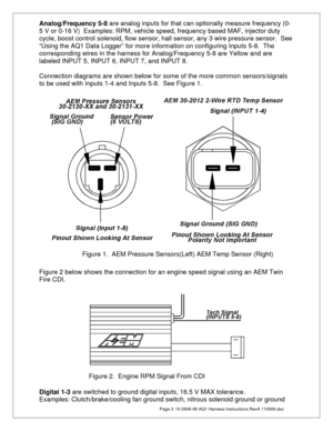
Analog/Frequency 5-8 are analog inputs for that can optionally measure frequency (0-
5 V or 0-16 V)  Examples: RPM, vehicle speed, frequency based MAF, injector duty
cycle, boost control solenoid, flow sensor, hall sensor, any 3 wire pressure sensor.  See
“Using the AQ1 Data Logger” for more information on configuring Inputs 5-8.  The
corresponding wires in the harness for Analog/Frequency 5-8 are Yellow and are
labeled INPUT 5, INPUT 6,...
Page 4
  Page 4  10-2906-96 AQ1 Harness Instructions RevA 110906.doc
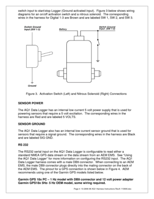
switch input to start/stop Logger (Ground activated input).  Figure 3 below shows wiring
diagrams for an on/off activation switch and a nitrous solenoid.  The corresponding
wires in the harness for Digital 1-3 are Brown and are labeled SW 1, SW 2, and SW 3.


SENSOR POWER

The AQ1 Data Logger has an internal low current 5 volt power supply that is used for
powering sensors that require a 5 volt excitation.  The corresponding...
Page 5
  Page 5  10-2906-96 AQ1 Harness Instructions RevA 110906.doc


CAN BUS 2

Not used with AQ1 Data Logger PN 30-2500

USB

The AQ1 Data Logger has two USB ports for easy connection and programming.   The
AQ1 Data Logger receives low voltage power from the USB port, allowing users to
access the SD card and make configuration changes at all times, 12 volt power is not
necessary.  The black remote mount USB port in the harness is designed for easy in
vehicle programming and data downloads....
Page 6
  Page 6  10-2906-96 AQ1 Harness Instructions RevA 110906.doc
30-2906-18 Connector Pinout

Pin Description Wire Stamping
1  Switched 12V  SW IGN
2  Switch to Ground Digital Input 1 (16V Max) SW 1
3  Switch to Ground Digital Input 2 (16V Max) SW 2
4  Switch to Ground Digital Input 3 (16V Max) SW 3
5 Ground/Sheild  NOT APPLICABLE
6  Permanent 12V  PERM PWR
7  Sensor Ground  SIG GND
8  Analog 1 (5V Max)  INPUT 1
9  Analog 2 (5V Max)  INPUT 2
10  Analog 3 (5V Max)  INPUT 3
11  Analog 4 (5V Max)...
Page 7
  Page 7  10-2906-96 AQ1 Harness Instructions RevA 110906.doc


RECOMMENDED PARTS

30-51XX Analog Style Gauges
30-44XX Digital Style Gauges
30-2340 4 Channel UEGO Controller
30-4100 Digital Gauge Style UEGO Controller
30-5130 Analog Gauge Style UEGO Controller
30-2310 Inline UEGO Controller
30-2320 X-Wifi
30-2130-XX Stainless Steel Body Pressure Sensor
30-2131-XX Brass Body Pressure Sensor
30-2010 GM Style Inlet Air Temp Sensor
30-2011 GM Style Coolant Temp Sensor
30-2012 Fluid Temp...


