Home
>
Addonics Technologies
>
Raid Tower
>
Addonics Technologies 4U RAID Rack RR2035ASDES user guide
Addonics Technologies 4U RAID Rack RR2035ASDES user guide
Here you can view all the pages of manual Addonics Technologies 4U RAID Rack RR2035ASDES user guide. The Addonics Technologies manuals for Raid Tower are available online for free. You can easily download all the documents as PDF.
Page 1
Technical Support
If you need any assistance to get your unit functioning properly, please have your
product information ready and contact Addonics Technical Support at:
Hours: 8:30 am - 6:00 pm PST
Phone: 408-453-6212
Email: http://www.addonics.com/support/query/
v8.1.11
T E C H N O L O G I E S
www.addonics.com
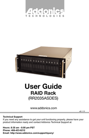
User Guide
RAID Rack
(RR2035ASDES)
Page 2
www.addonics.comTechnical Support (M-F 8:30am - 6:00pm PST)    Phone: 408-453-6212  Email: www.addonics.com/support/query/
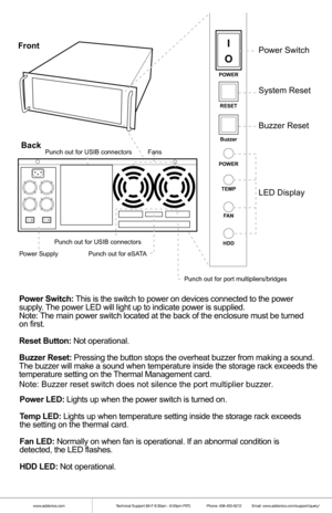
POWER
RESET
Buzzer
POWER TEMP
F AN
HDD
I
OPower Switch
System Reset
Buzzer Reset
LED Display
I
OI
O
Punch out for port multipliers/bridges
FansPunch out for USIB connectors
Front
Back
Power Switch : T his  is the  swit ch to power  on devic es connect ed to the  power
supply . T he  power  LE D  will  light  up to indicat e power  is supplied.
Not e: T he  main  power s witch  locat...
Page 3
www.addonics.comTechnical Support (M-F 8:30am - 6:00pm PST)    Phone: 408-453-6212  Email: www.addonics.com/support/query/
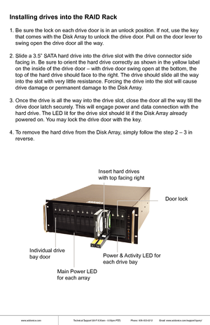
1. Be sure the lock on each drive door is in an unlock position. If not,\
 use the key
    that comes with the Disk Array to unlock the drive door. Pull on the door lever to
    swing open the drive door all the way.
2. Slide a 3.5” SATA hard drive into the drive slot with the drive connector side
    facing in. Be sure to orient the hard drive correctly as shown in th\
e yellow...
Page 4
www.addonics.comTechnical Support (M-F 8:30am - 6:00pm PST)    Phone: 408-453-6212  Email: www.addonics.com/support/query/
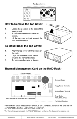
How  to  Remo ve th e T op  Cover:
1.  Locate the  2 screws  at the  back  of the
  storage  rack
2 .  Turn  screws  counterclockwise t o
  loosen.
3 .  Lift the t op cover  and pull t owards t he
  rear end of the  rack.
To  Mount  Back  th e T op  Cover:
1.  Align t he top cover  with the  edges  of
  the  rack.
2 .  Lay it flat  on the rack  and slide  it
  towards...
Page 5
www.addonics.comTechnical Support (M-F 8:30am - 6:00pm PST)    Phone: 408-453-6212  Email: www.addonics.com/support/query/
RAID Setting Button
Dip SwitchSATA Host Port (Port 5) SATA Port 2
SATA Port 1
SATA Port 0
SATA Port 3
SATA Port 4
Drive activity LED Jumper Block (J1)
Error LED Jumper Block (J3)
Floppy
Power
Connector
Dip Switch Settings
Enable
ERR Buzzer
Function
Auto-
Rebuilding
to Spare
Drive Port Multiplier Mode
Raid Mode
1               2     3                4               5
Individual...
Page 6
www.addonics.comTechnical Support (M-F 8:30am - 6:00pm PST)    Phone: 408-453-6212  Email: www.addonics.com/support/query/
Default factory DIP Switch setting:
SW1 – RAID Setting DIP Switch
BZS –   Error buzzer function
EZ   –   Automatic rebuilding to spare drive (one of the drives on the raid is s\
et as a
  spare). If EZ is ENABLED anda drive failure occurs, the spare will auto\
matically
  act as a drive replacement and rebuilding will automatically start.
M2  –   RAID mode 2
M1  –   RAID mode...
Page 7
www.addonics.comTechnical Support (M-F 8:30am - 6:00pm PST)    Phone: 408-453-6212  Email: www.addonics.com/support/query/
Cable Connections
1.  Attach the SATA hard drives (up to 5) to the SATA ports on the Hardware
  Port Multiplier (HPM) using SATA cables. It is recommended to connect
  drives to the SATA ports 1 to 5 successively.
2.  To provide power to the HPM, connect a 4-pin floppy power cable from the \

  system power supply to the floppy power connector on the HPM.
3.  Optional:...
Page 8
www.addonics.comTechnical Support (M-F 8:30am - 6:00pm PST)    Phone: 408-453-6212  Email: www.addonics.com/support/query/
Cable Connections
1.  Attach the SATA hard drives (up to 5) to the SATA ports on the Hardware
  Port Multiplier (HPM) using SATA cables. It is recommended to connect
  drives to the SATA ports 1 to 5 successively.
2.  To provide power to the HPM, connect a 4-pin floppy power cable from the \

  system power supply to the floppy power connector on the HPM.
3.  Optional:...
Page 9
www.addonics.comTechnical Support (M-F 8:30am - 6:00pm PST)    Phone: 408-453-6212  Email: www.addonics.com/support/query/
  f.  Press the RAID setting button with a ball point pen.
  g.  While pressing the RAID setting button turn on the system power
    where the HPM is connected. The buzzer will sound while holding the
    RAID setting button. Release it after at least 5 seconds for hardware
    initialization. A single beep will be heard to indicate initialization is
  completed.
  h....
Page 10
www.addonics.comTechnical Support (M-F 8:30am - 6:00pm PST)    Phone: 408-453-6212  Email: www.addonics.com/support/query/
Cable Connections
1.  Attach the SATA hard drives (up to 5) to the SATA ports on the Hardware
  Port Multiplier (HPM) using SATA cables. It is recommended to connect
  drives to the SATA ports 1 to 5 successively.
2.  To provide power to the HPM, connect a 4-pin floppy power cable from the \

  system power supply to the floppy power connector on the HPM.
3.  Optional:...


