Acer Aspire 1710 Service Guide
Here you can view all the pages of manual Acer Aspire 1710 Service Guide. The Acer manuals for Notebook are available online for free. You can easily download all the documents as PDF.
Page 1
Acer Aspire 1710 Series
Service Guide
Project Code: A15
Please note that Aspire 1710 has the same housing with Aspire 1700. And this model will not have service CD.
Please refer to Aspire 1700 service CD (Part No.: VD.A08V7.001) for disassembling mpeg files.
                                                                                                                                       PRINTED IN TAIWAN
Page 2
II
Revision History
Please refer to the table below for the updates made on Aspire 1710 service guide.
Date Chapter Updates
Page 3
III
Copyright
Copyright © 2004 by Acer Incorporated.   All rights reserved.  No part of this publication may be reproduced,
transmitted, transcribed, stored in a retrieval system, or translated into any language or computer language, in
any form or by any means, electronic, mechanical, magnetic, optical, chemical, manual or otherwise, without
the prior written permission of Acer Incorporated.
Disclaimer
The information in this guide is subject to change without notice.
Acer Incorporated makes no...
Page 4
IV
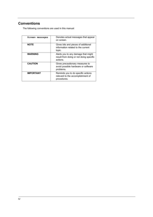
Conventions
The following conventions are used in this manual:
Screen messagesDenotes actual messages that appear
on screen.
NOTEGives bits and pieces of additional
information related to the current
topic.
WARNINGAlerts you to any damage that might
result from doing or not doing specific
actions.
CAUTIONGives precautionary measures to
avoid possible hardware or software
problems.
IMPORTANTReminds you to do specific actions
relevant to the accomplishment of
procedures.
Page 5
V
Preface
Before using this information and the product it supports, please read the following general information.
1.This Service Guide provides you with all technical information relating to the BASIC CONFIGURATION
decided for Acer global product offering. To better fit local market requirements and enhance product
competitiveness, your regional office MAY have decided to extend the functionality of a machine (e.g.
add-on card, modem, or extra memory capability). These LOCALIZED FEATURES will NOT be...
Page 7
VII
Table of Contents
Chapter 1 System Introduction  1
Features  . . . . . . . . . . . . . . . . . . . . . . . . . . . . . . . . . . . . . . . . . . . . . . . . . . . . . . . . . . . .1
Display   . . . . . . . . . . . . . . . . . . . . . . . . . . . . . . . . . . . . . . . . . . . . . . . . . . . . . . . . . . . . .3
System Block Diagram  . . . . . . . . . . . . . . . . . . . . . . . . . . . . . . . . . . . . . . . . . . . . . . . . .4
Board Layout   . . . . . . . . . . . . . . . . . . . . . . . . . . ....
Page 8
VIII
Table of Contents
Remove the side bracket   . . . . . . . . . . . . . . . . . . . . . . . . . . . . . . . . . . . . . . . . . .57
Remove the LED cable attached on the LCD outer shield  . . . . . . . . . . . . . . . . .58
Remove the subwoofer  . . . . . . . . . . . . . . . . . . . . . . . . . . . . . . . . . . . . . . . . . . . .58
Release the MDC cable   . . . . . . . . . . . . . . . . . . . . . . . . . . . . . . . . . . . . . . . . . . .59
Disconnect the cable to the modem header  . . . . . . . . ....
Page 10
Chapter 11
Features
This computer was designed with the user in mind. Here are just a few of its many features:
Performance
TIntel® Pentium® 4 FSB 800 processors
TL2 cache 1MB
TIntel 865G with ICH-5, support 800MHz Front Side Bus, dual channel and HTT support
T80 GB or higher-capacity Desktop 5400rpm, 7200rpm HDD
TMicrosoft® Windows® XP Home/Pro operating system
TOptional 6-in-1 Multimedia memory card reader module
Multimedia
TDVD/CD-RW combo
TDVD Dual drive
TAudio input and output jacks
THardware 3D...


